Steam traps
Thermodynamic
Size
A
B
Screwed Socket
Flanged
weld
ASME 150, 300, 600
PN40
PN100
C D E
Withdrawal
distance
F
Withdrawal
distance
1⁄2" DN15
58 78 92
150
210
61 59 40 30
3⁄4" DN20
61 95 92
150
210
61 63 40 30
1" DN25 65 95 92
160
230 61 67 40 30
5.7.31
Size
Screwed Socket weld
Flanged
ASME 150
ASME 300
ASME 600
PN40
PN100
1⁄2" DN15
1.38 1.49 2.46 2.96
3.06
3.06 4.36
3⁄4" DN20
1.64 1.64 3.16 4.06
4.26
3.96 6.26
1" DN25 1.90 1.90 4.16 5.16
5.46 4.86 8.16
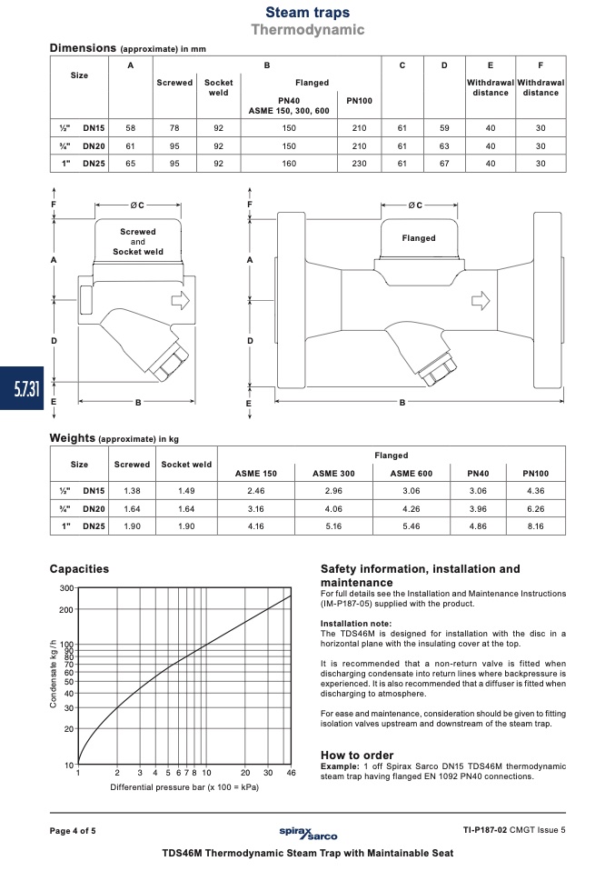
Dimensions (approximate) in mm
F
Ø
C
F
ØC
Screwed
and
A
Socket weld
A
D
D
Flanged
E
B
E
B
Weights (approximate) in kg
Capacities
������
������
������
����
����
����
����
����
����
����
����
����
��
�
�
�
�
��������������
���
�
���
�
����
Differential pressure bar (x 100 = kPa)
Safety information, installation and
maintenance
For full details see the Installation and Maintenance Instructions
(IM-P187-05) supplied with the product.
Installation note:
The TDS46M is designed for installation with the disc in a
horizontal plane with the insulating cover at the top.
It is recommended that a non-return valve is fitted when
discharging condensate into return lines where backpressure is
experienced. It is also recommended that a diffuser is fitted when
discharging to atmosphere.
For ease and maintenance, consideration should be given to fitting
isolation valves upstream and downstream of the steam trap.
How to order
Example: 1 off Spirax Sarco DN15 TDS46M thermodynamic
steam trap having flanged EN 1092 PN40 connections.
Page 4 of 5
TI-P187-02 CMGT Issue 5
TDS46M Thermodynamic Steam Trap with Maintainable Seat
C
o
n
d
e
n
s
a
t
e
k
g
/
h

