Steam traps
Thermodynamic
5.7.23
Steam
saturation
curve
C
Steam
saturation
curve
B
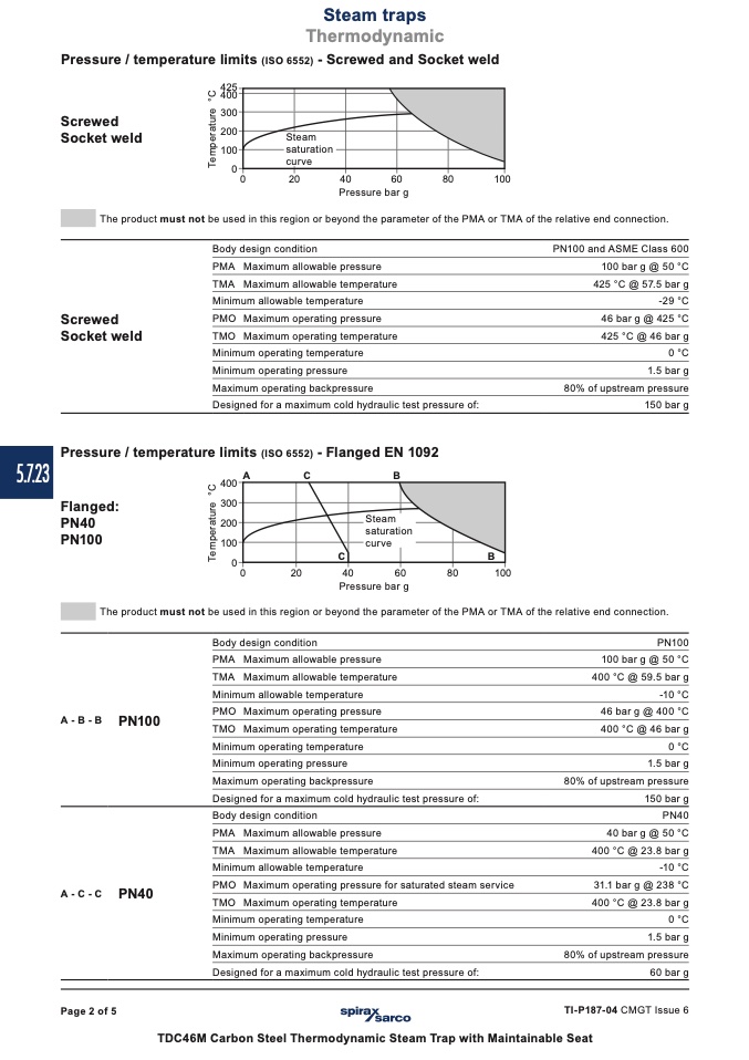
Pressure / temperature limits (ISO 6552) - Screwed and Socket weld
Screwed
Socket weld
425
400
300
200
100
0
0
20
40
60
80
100
Pressure bar g
The product must not be used in this region or beyond the parameter of the PMA or TMA of the relative end connection.
Screwed
Socket weld
Body design condition
PMA Maximum allowable pressure
TMA Maximum allowable temperature
Minimum allowable temperature
PMO Maximum operating pressure
TMO Maximum operating temperature
Minimum operating temperature
Minimum operating pressure
Maximum operating backpressure
Designed for a maximum cold hydraulic test pressure of:
PN100 and ASME Class 600
100 bar g @ 50 °C
425 °C @ 57.5 bar g
-29 °C
46 bar g @ 425 °C
425 °C @ 46 bar g
0 °C
1.5 bar g
80% of upstream pressure
150 bar g
Pressure / temperature limits (ISO 6552) - Flanged EN 1092
400
A
C
B
100
0
0
20
40
60
80
100
Pressure bar g
300
PN40
200
Flanged:
PN100
The product must not be used in this region or beyond the parameter of the PMA or TMA of the relative end connection.
A-B-B
PN100
Body design condition
PMA Maximum allowable pressure
TMA Maximum allowable temperature
Minimum allowable temperature
PMO Maximum operating pressure
TMO Maximum operating temperature
Minimum operating temperature
Minimum operating pressure
Maximum operating backpressure
Designed for a maximum cold hydraulic test pressure of:
Body design condition
PMA Maximum allowable pressure
TMA Maximum allowable temperature
Minimum allowable temperature
PMO Maximum operating pressure for saturated steam service
TMO Maximum operating temperature
Minimum operating temperature
Minimum operating pressure
Maximum operating backpressure
Designed for a maximum cold hydraulic test pressure of:
PN100
100 bar g @ 50 °C
400 °C @ 59.5 bar g
-10 °C
46 bar g @ 400 °C
400 °C @ 46 bar g
0 °C
1.5 bar g
80% of upstream pressure
150 bar g
PN40
40 bar g @ 50 °C
400 °C @ 23.8 bar g
-10 °C
31.1 bar g @ 238 °C
400 °C @ 23.8 bar g
0 °C
1.5 bar g
80% of upstream pressure
60 bar g
A-C-C
PN40
Page 2 of 5
TI-P187-04 CMGT Issue 6
TDC46M Carbon Steel Thermodynamic Steam Trap with Maintainable Seat
T
e
m
p
e
r
a
t
u
r
e
°
C
T
e
m
p
e
r
a
t
u
r
e
°
C

