Steam traps
Ball float
5.5.111
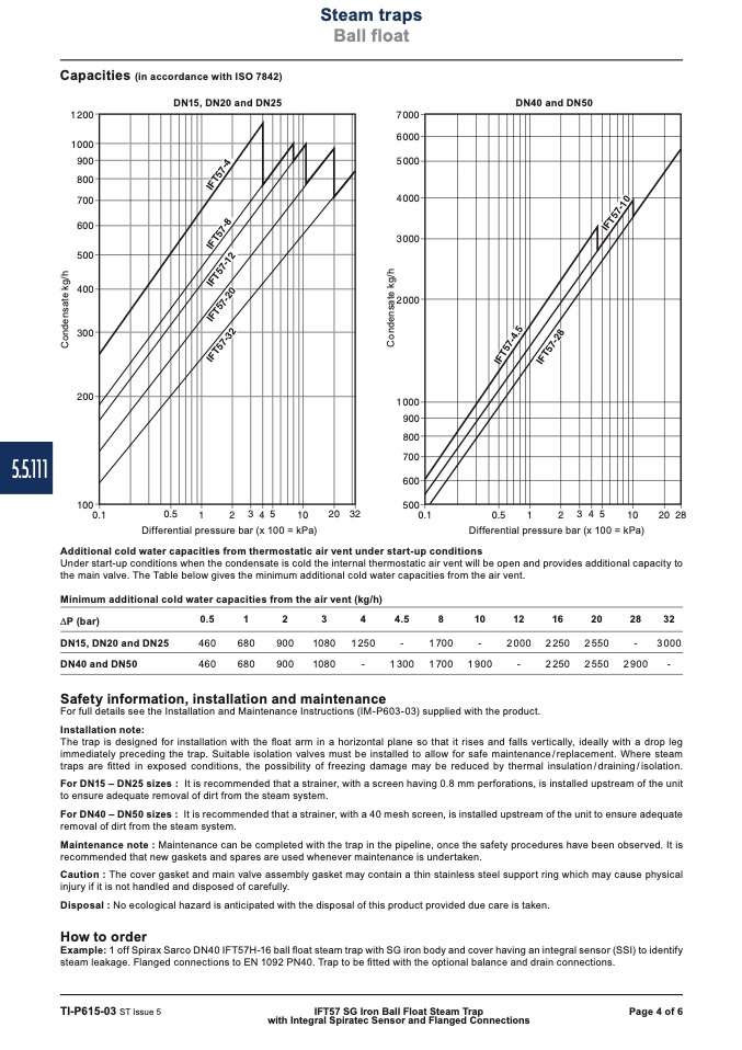
Capacities (in accordance with ISO 7842)
�� ������
��������
������
������
������
������
������
������
������
������
������
������
������
��
�� �� �� ��
����
���� ����
�� ������
�� ������
�� ������
�� ������
�� ������
�� ������
�� ������
������
������
������
������
������
������
������
��
�� �� �� ��
����
���� ����
DN15, DN20 and DN25
DN40 and DN50
Differential pressure bar (x 100 = kPa)
Differential pressure bar (x 100 = kPa)
Additional cold water capacities from thermostatic air vent under start-up conditions
Under start-up conditions when the condensate is cold the internal thermostatic air vent will be open and provides additional capacity to
the main valve. The Table below gives the minimum additional cold water capacities from the air vent.
Minimum additional cold water capacities from the air vent (kg/h)
P (bar)
0.5
1
2
3
4
4.5
8
10
12
16
20
28
32
DN15, DN20 and DN25
460
680
900
1080 1250
-
1700
-
2000 2250
DN40 and DN50
460
680
900
1080
-
1300 1700 1900
-
2250
Safety information, installation and maintenance
For full details see the Installation and Maintenance Instructions (IM-P603-03) supplied with the product.
Installation note:
2550
-
3000
2550 2900
-
The trap is designed for installation with the float arm in a horizontal plane so that it rises and falls vertically, ideally with a drop leg
immediately preceding the trap. Suitable isolation valves must be installed to allow for safe maintenance/replacement. Where steam
traps are fitted in exposed conditions, the possibility of freezing damage may be reduced by thermal insulation/draining/isolation.
For DN15 – DN25 sizes : It is recommended that a strainer, with a screen having 0.8 mm perforations, is installed upstream of the unit
to ensure adequate removal of dirt from the steam system.
For DN40 – DN50 sizes : It is recommended that a strainer, with a 40 mesh screen, is installed upstream of the unit to ensure adequate
removal of dirt from the steam system.
Maintenance note : Maintenance can be completed with the trap in the pipeline, once the safety procedures have been observed. It is
recommended that new gaskets and spares are used whenever maintenance is undertaken.
Caution : The cover gasket and main valve assembly gasket may contain a thin stainless steel support ring which may cause physical
injury if it is not handled and disposed of carefully.
Disposal : No ecological hazard is anticipated with the disposal of this product provided due care is taken.
How to order
Example: 1 off Spirax Sarco DN40 IFT57H-16 ball float steam trap with SG iron body and cover having an integral sensor (SSI) to identify
steam leakage. Flanged connections to EN 1092 PN40. Trap to be fitted with the optional balance and drain connections.
TI-P615-03 ST Issue 5
IFT57 SG Iron Ball Float Steam Trap
Page 4 of 6
with Integral Spiratec Sensor and Flanged Connections
C
o
n
d
e
n
s
a
t
e
k
g
/
h
C
o
n
d
e
n
s
a
t
e
k
g
/
h
����
����������������
����������������
�
�
�
�
�
�
�
�
�
�
�
�
�
�
�
�
�
�
�
�
�
�
�
�
�
�
�
�
�
�
�
�
�
�

