Certification
This product is available with certification to EN 10204 3.1.
Note: All certification / inspection requirements must be stated at
the time of order placement.
Sizes and pipe connections
DN15, DN20, DN25, DN40 and DN50.
Standard flange EN 1092 PN40 (formerly DIN 2501).
Face-to-face dimensions to BS EN 26554 Series 1.
Optional extras
If requested at the point of order the cover can be drilled and tapped
for the purpose of fitting a balance line and drain cock.
Pressure/temperature limits
8
9
7
3
4
Materials
No. Part
1 Body
2 Cover
3 Cover gasket
Cover bolts
4 Cover studs
Covernuts
������
������
������
������
������
��
Steam
saturation
curve
��
����
����
��������
����
Pressure bar g
The product must not be used in this region.
The product should not be used in this region due to the
PN40
40 bar g @ 50°C
400°C @ 24 bar g
-10°C
31 bar g
240°C @ 31 bar g
Material
limitations of the sensor.
Body design conditions
Carbon steel
1.0619+N
Carbon steel
1.0619+N
Reinforced exfoliated graphite
PMA Maximum allowable pressure
TMA Maximum allowable temperature
Minimum allowable temperature
PMO
Maximum operating pressure
for saturated steam service
TMO Maximum operating temperature
Minimum operating temperature
FT54H Steel
FT54V Steel
FT54V Steel
24 CrMo 5 (1.7258)
24 Cr Mo 5 (1.7258)
CK35(1.1181)
X 22 CrNi 17 2 (1.4057)
X 105 CrMo 17 (1.4125)
X 22 CrNi 17 2 (1.4057)
X 22 CrNi 17 2 (1.4057)
0°C
Note: For lower operating temperatures consult Spirax Sarco
5 Valve seat (DN15 - 25) Stainless steel
6 Valve
(DN15- 25) Stainless steel
7 Valve seat (DN40 - 50) Stainless steel
8 Valve
(DN40 - 50) Stainless steel
DPMX Maximum differential pressure
See overleaf
Designed for a maximum cold hydraulic test pressure of 60 bar g
Caution: The trap in its complete operational form must not be
subjected to a pressure of greater than 48 bar otherwise damage to
the internal mechanism may result.
9 Main valve gasket
10 Ball float
11 Ball float
24 Sensor gasket
Exfoliated graphite
Steam traps
Ball float
Local regulations may restrict the use of this product to below the conditions quoted.
In the interests of development and improvement of the product, we reserve the right to change the specification without notice.
© Copyright 2013
IFT54 Carbon Steel
Ball Float Steam Trapwith Integral
Spiratec Sensor and Flanged Connections
Description
The IFT54 is a carbon steel ball float steam trap
fitted with an
integral Spiratec sensor (SSI) for steam leakage detection and
integral thermostatic air vent for the prompt removal of large
condensate loads from steam systems. The trap is supplied with
integrally flanged connections (for horizontal or vertical installation)
and can be maintained without disturbing the pipework. Body and
cover are produced by TÜV approved foundries.
Available options: IFT54H - Horizontal flow. IFT54V - Vertical flow.
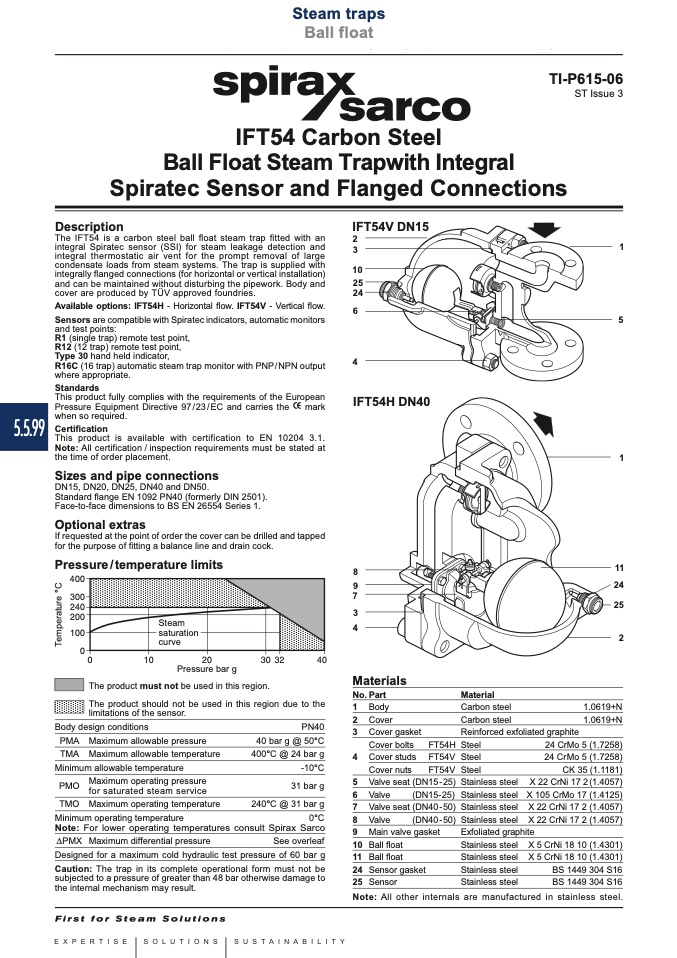
IFT54V DN15
2
3
1
Sensors are compatible with Spiratec indicators, automatic monitors
and test points:
R1 (single trap) remote test point,
R12 (12 trap) remote test point,
10
25
24
6
4
IFT54H DN40
5
1
11
24
25
2
Type 30 hand held indicator,
R16C (16 trap) automatic steam trap monitor with PNP/NPN output
where appropriate.
Standards
This product fully complies with the requirements of the European
Pressure Equipment Directive 97/23/EC and carries the mark
5.5.99
when so required.
Stainless steel
Stainless steel
Stainless steel
Stainless steel
X 5 CrNi 18 10 (1.4301)
X 5 CrNi 18 10 (1.4301)
BS 1449 304 S16
BS 1449 304 S16
Note: All other internals are manufactured in stainless steel.
25 Sensor
TI-P615-06
ST Issue 3
T
e
m
p
e
r
a
t
u
r
e
°
C

