Hydraulic separator DN 32 (11⁄4")
H
y
d
r
a
u
l
i
c
s
e
p
a
r
a
t
o
r
D
N
3
2
(
1
1⁄
4
"
)
Hydraulic separator DN 32 (11⁄4")
Flow rate: 2600 l/h
Completely made of brass, with separate flow and return line, for the installation under an
individual HeatBloC® DN 32. With EPP insulation.
Can also be installed under a modular distribution manifold DN 32 (with mounting plate item no.
3725) or separately (in the pipe). In case of separate installation you need two connection sets item
no. 2152.
Connections:
11⁄4" PAW flange for 2" nut (top),
2" external thread, flat-sealing with fitting,
width = 330 mm
installation height = 125 mm
centre distance = 125 mm
374203
Flow rate: 4800 l/h
Completely made of brass, completely insulated with EPP insulation, for the installation under a
modular distribution manifold DN 32 or separately (vertically or horizontally) to the wall.
Connections:
11⁄4" PAW flange for 2" nut (top),
11⁄4" internal thread / 2" external thread, flat-sealing (bottom) with fitting,
2 x 1⁄2" internal thread for immersion sleeve and fill and drain valve,
width = 600 mm
installation height = 200 mm
centre distance = 375 mm
374213
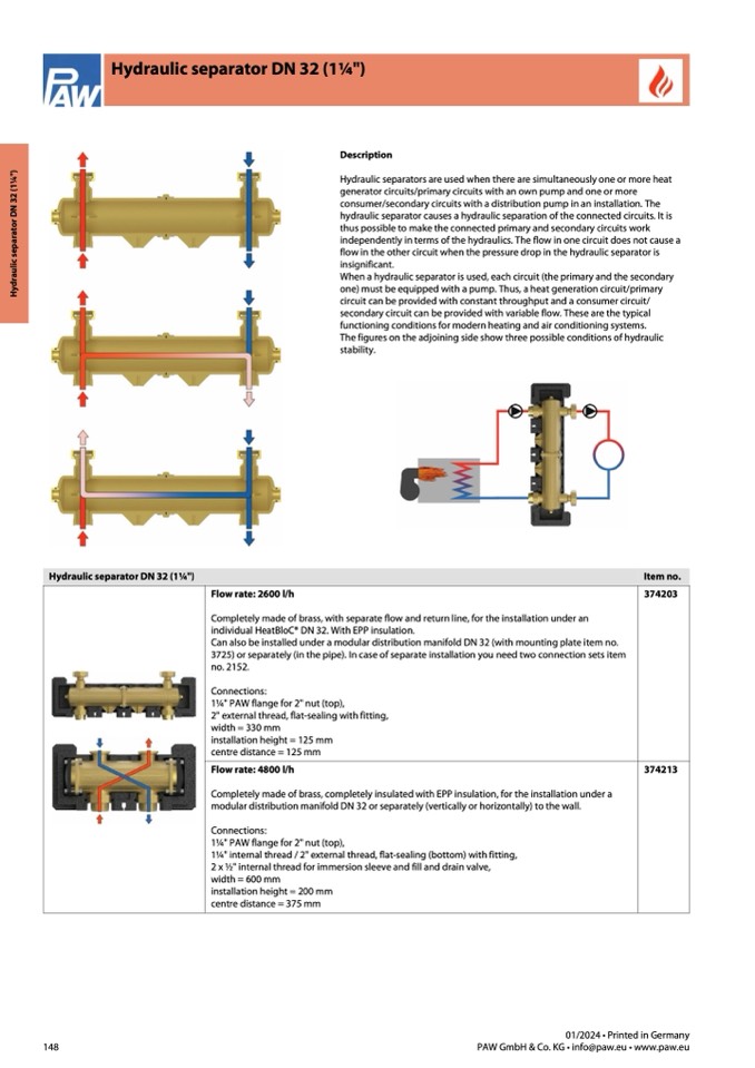
Description
Hydraulic separators are used when there are simultaneously one or more heat
generator circuits/primary circuits with an own pump and one or more
consumer/secondary circuits with a distribution pump in an installation. The
hydraulic separator causes a hydraulic separation of the connected circuits. It is
thus possible to make the connected primary and secondary circuits work
independently in terms of the hydraulics. The flow in one circuit does not cause a
flow in the other circuit when the pressure drop in the hydraulic separator is
insignificant.
When a hydraulic separator is used, each circuit (the primary and the secondary
one) must be equipped with a pump. Thus, a heat generation circuit/primary
circuit can be provided with constant throughput and a consumer circuit/
secondary circuit can be provided with variable flow. These are the typical
functioning conditions for modern heating and air conditioning systems.
The figures on the adjoining side show three possible conditions of hydraulic
stability.
Item no.
148
01/2024 • Printed in Germany
PAW GmbH & Co. KG • info@paw.eu • www.paw.eu

