Hydraulic separator DN 20 (
3⁄4")
H
y
d
r
a
u
l
i
c
s
e
p
a
r
a
t
o
r
D
N
2
0
(
3⁄
4
"
)
Hydraulic separator DN 20 (3⁄4")
Flow rate: 950 l/h
Completely made of brass, with separate flow and return line, for the installation under an
individual HeatBloC® DN 20. The EPP insulation is integrated into the HeatBloC.
Can also be installed under a modular distribution manifold DN 20 (with mounting plate item no.
3125) or separately (in the pipe).When installing separately two additional union nuts item no. 2055
are necessary and the insulation must be produced on site.
Connections:
3⁄4" PAW flange for nut 1" nut (top),
3⁄4" internal thread x 1" external thread flat-sealing (bottom),
2 x 3⁄4" internal thread, closed with plug (on the side),
width = 260 mm,
installation height = 80 mm,
centre distance = 90 mm
3142
Flow rate: 2200 l/h
Completely made of brass, completely insulated with EPP insulation, for the installation under a
modular distribution manifold DN 20 or separately (vertically or horizontally) to the wall.
Connections:
3⁄4" PAW flange for nut 1" nut (top),
3⁄4" internal thread x 1" external thread flat-sealing (bottom), 2 x for boiler connection, others closed
with plug,
2 × 1⁄2" internal thread for immersion sleeve and fill and drain valve
width = 435 mm,
installation height = 120 mm,
centre distance = 270 mm
31421
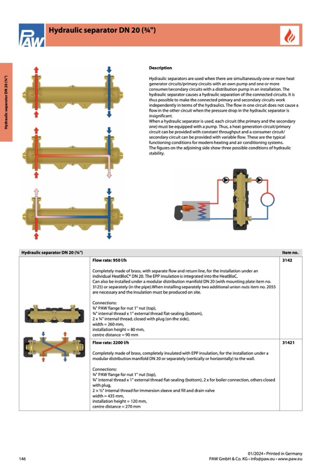
Description
Hydraulic separators are used when there are simultaneously one or more heat
generator circuits/primary circuits with an own pump and one or more
consumer/secondary circuits with a distribution pump in an installation. The
hydraulic separator causes a hydraulic separation of the connected circuits. It is
thus possible to make the connected primary and secondary circuits work
independently in terms of the hydraulics. The flow in one circuit does not cause a
flow in the other circuit when the pressure drop in the hydraulic separator is
insignificant.
When a hydraulic separator is used, each circuit (the primary and the secondary
one) must be equipped with a pump. Thus, a heat generation circuit/primary
circuit can be provided with constant throughput and a consumer circuit/
secondary circuit can be provided with variable flow. These are the typical
functioning conditions for modern heating and air conditioning systems.
The figures on the adjoining side show three possible conditions of hydraulic
stability.
Item no.
146
01/2024 • Printed in Germany
PAW GmbH & Co. KG • info@paw.eu • www.paw.eu

