ELETTROVALVOLE
GAS SOLENOID VALVES
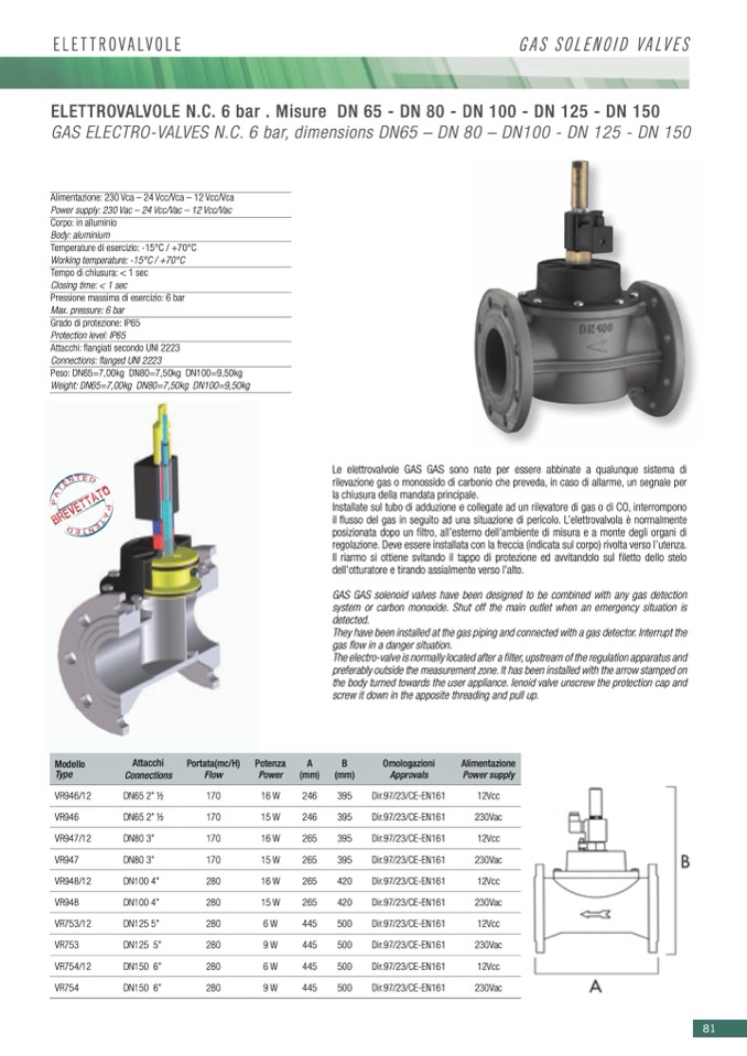
ELETTROVALVOLEN.C.6bar.Misure DN65-DN80-DN100-DN125-DN150
GAS ELECTRO-VALVES N.C. 6 bar, dimensions DN65 – DN 80 – DN100 - DN 125 - DN 150
Alimentazione: 230 Vca – 24 Vcc/Vca – 12 Vcc/Vca
Power supply: 230 Vac – 24 Vcc/Vac – 12 Vcc/Vac
Corpo: in alluminio
Body: aluminium
Temperature di esercizio: -15°C / +70°C
Working temperature: -15°C / +70°C
Tempo di chiusura: < 1 sec
Closing time: < 1 sec
Pressione massima di esercizio: 6 bar
Max. pressure: 6 bar
Grado di protezione: IP65
Protection level: IP65
Attacchi: flangiati secondo UNI 2223
Connections: flanged UNI 2223
Peso:DN65=7,00kg DN80=7,50kg DN100=9,50kg
Weight:DN65=7,00kg DN80=7,50kg DN100=9,50kg
Modello
Type
VR946/12
VR946
VR947/12
VR947
VR948/12
VR948
VR753/12
VR753
VR754/12
VR754
A
B
(mm) (mm)
246
395
246
395
265
395
265
395
265
420
265
420
445
500
445
500
445
500
445
500
Alimentazione
Power supply
12Vcc
230Vac
12Vcc
230Vac
12Vcc
230Vac
12Vcc
230Vac
12Vcc
230Vac
Attacchi
Connections
DN65 2” 1⁄2
DN65 2” 1⁄2
DN80 3”
DN80 3”
DN100 4”
DN100 4”
DN125 5”
DN125 5”
DN150 6”
DN150 6”
Portata(mc/H) Potenza
Flow
Power
170
16W
170
15W
170
16W
170
15W
280
16W
280
15W
280
6W
280
9W
280
6W
280
9W
Le elettrovalvole GAS GAS sono nate per essere abbinate a qualunque sistema di
rilevazione gas o monossido di carbonio che preveda, in caso di allarme, un segnale per
la chiusura della mandata principale.
Installate sul tubo di adduzione e collegate ad un rilevatore di gas o di CO, interrompono
il flusso del gas in seguito ad una situazione di pericolo. L’elettrovalvola è normalmente
posizionata dopo un filtro, all’esterno dell’ambiente di misura e a monte degli organi di
regolazione. Deve essere installata con la freccia (indicata sul corpo) rivolta verso l’utenza.
Il riarmo si ottiene svitando il tappo di protezione ed avvitandolo sul filetto dello stelo
dell'otturatore e tirando assialmente verso l’alto.
GAS GAS solenoid valves have been designed to be combined with any gas detection
system or carbon monoxide. Shut off the main outlet when an emergency situation is
detected.
They have been installed at the gas piping and connected with a gas detector. Interrupt the
gas flow in a danger situation.
The electro-valve is normally located after a filter, upstream of the regulation apparatus and
preferably outside the measurement zone. It has been installed with the arrow stamped on
the body turned towards the user appliance. lenoid valve unscrew the protection cap and
screw it down in the apposite threading and pull up.
Omologazioni
Approvals
Dir.97/23/CE-EN161
Dir.97/23/CE-EN161
Dir.97/23/CE-EN161
Dir.97/23/CE-EN161
Dir.97/23/CE-EN161
Dir.97/23/CE-EN161
Dir.97/23/CE-EN161
Dir.97/23/CE-EN161
Dir.97/23/CE-EN161
Dir.97/23/CE-EN161
81

