ELETTROVALVOLE
GAS SOLENOID VALVES
Modello
Type
Attacchi
Connections
Portata(mc/H)
Flow
Potenza
Power
A
(mm)
B
(mm)
Omologazioni
Approvals
Alimentazione
Power supply
76
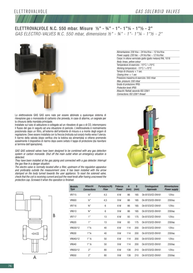
ELETTROVALVOLE N.C. 550 mbar. Misure 1⁄2” - 3⁄4” - 1”- 1”1⁄4 - 1”1⁄2 - 2”
GAS ELECTRO-VALVES N.C. 550 mbar, dimensions 1⁄2” - 3⁄4” - 1”- 1”1⁄4 - 1”1⁄2 - 2”
Alimentazione: 230 Vca – 24 Vcc/Vca – 12 Vcc/Vca
Power supply: 230 Vac – 24 Vcc/Vac – 12 Vcc/Vac
Corpo: in ottone verniciato giallo (giallo metano) RAL 1018
Body: brass, yellow colour
Temperature di esercizio: -15°C / +70°C
Working temperature: -15°C / +70°C
Tempo di chiusura: < 1 sec
Closing time: < 1 sec
Pressione massima di esercizio: 550 mbar
Max. pressure: 550 mbar
Grado di protezione: IP65
Protection level: IP65
Attacchi: filettati secondo ISO 228/1
Connections: ISO 228/1 thread
Le elettrovalvole GAS GAS sono nate per essere abbinate a qualunque sistema di
rilevazione gas o monossido di carbonio che preveda, in caso di allarme, un segnale per
la chiusura della mandata principale.
Installate sul tubo di adduzione e collegate ad un rilevatore di gas o di CO, interrompono
il flusso del gas in seguito ad una situazione di pericolo. L’elettrovalvola è normalmente
posizionata dopo un filtro, all’esterno dell’ambiente di misura e a monte degli organi di
regolazione. Deve essere installata con la freccia (indicata sul corpo) rivolta verso l’utenza.
Il riarmo della valvola (dopo verifica che la bobina sia alimentata) si ottiene premendo
assialmente il dispositivo di riarmo dopo avere svitato il tappo di protezione (da riavvitare
al termine dell’operazione).
GAS GAS solenoid valves have been designed to be combined with any gas detection
system or carbon monoxide. Shut off the main outlet when an emergency situation is
detected.
They have been installed at the gas piping and connected with a gas detector. Interrupt
the gas flow in a danger situation.
The electro-valve is normally located after a filter, upstream of the regulation apparatus
and preferably outside the measurement zone. It has been installed with the arrow
stamped on the body turned towards the user appliance. To reset the solenoid valve,
check that the coil is receiving current and pull the reset knob after having unscrewed the
protection cap. Screwed it when the operation is finished.
VR715
1⁄2”
4,5
VR600
1⁄2”
4,5
VR716
3⁄4”
6
VR610
3⁄4”
6
6W
86
165
9W
86
165
6W
86
165
9W
86
165
6W
93
175
9W
93
175
6W
114
200
9W
114
200
6W
114
200
9W
114
200
6W
138
210
9W
138
210
Dir.97/23/CE-EN161
Dir.97/23/CE-EN161
Dir.97/23/CE-EN161
Dir.97/23/CE-EN161
Dir.97/23/CE-EN161
Dir.97/23/CE-EN161
Dir.97/23/CE-EN161
Dir.97/23/CE-EN161
Dir.97/23/CE-EN161
Dir.97/23/CE-EN161
Dir.97/23/CE-EN161
Dir.97/23/CE-EN161
12Vcc
230Vac
12Vcc
230Vac
12Vcc
230Vac
12Vcc
230Vac
12Vcc
230Vac
12Vcc
VR717
1”
VR620
1”
VR630/12
1”1⁄4
VR630
1”1⁄4
VR640/12
1” 1⁄2
VR640
1” 1⁄2
VR650/12
2”
VR650
2”
13
13
40
40
50
50
80
80
230Vac

