Technical characteristics
Hydraulic separator
Manifold connection
Manifold side centre distance
Boiler connection
Boiler side centre distance
Lower connection for boiler probe
Recommended primary circuit flow rate
Maximum primary circuit flow rate
Total maximum secondary circuit flow rate
Protection box
Thermal insulation
Insulation thickness
Insulating box section
Length
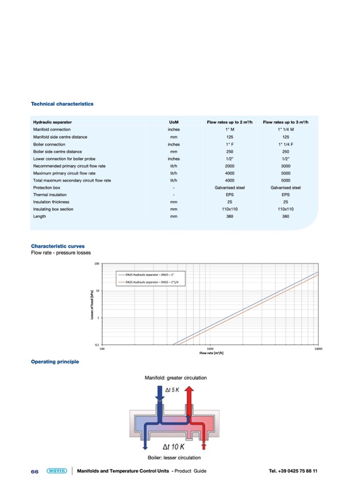
Characteristic curves
Flow rate - pressure losses
UoM
inches
mm
inches
mm
inches
lit/h
lit/h
lit/h
-
-
mm
mm
mm
Flow rates up to 2 m
3
/h
1" M
125
1" F
250
1/2"
2000
4000
4000
Galvanised steel
EPS
25
110x110
380
Flow rates up to 3 m
3
/h
1" 1/4 M
125
Operating principle
Manifold: greater circulation
1" 1/4
250
1/2"
F
3000
5000
5000
Galvanised steel
EPS
25
110x110
380
100
10
1
0,1
DN25 Hydraulic separator – DN25 – 1”
100
1000
10000
Flow rate [m3/h]
DN25 H ydraulic separator – DN2 5 – 1”1/4
L
o
s
s
e
s
o
f
h
e
a
d
[
k
P
a
]
Boiler: lesser circulation
66
Manifolds and Temperature Control Units - Product Guide
Tel. +39 0425 75 88 11

