6. Hydraulic separator
Hydraulic separators
Code
11 73 21
11 73 31
Specifications
Flow rate
m
3
/h
2
3
Boiler connec-
tions
1" F
1"1/4 F
User
connections
1" M
1"1/4 M
A
B
H
mm
mm
mm
382
110
110
382
110
110
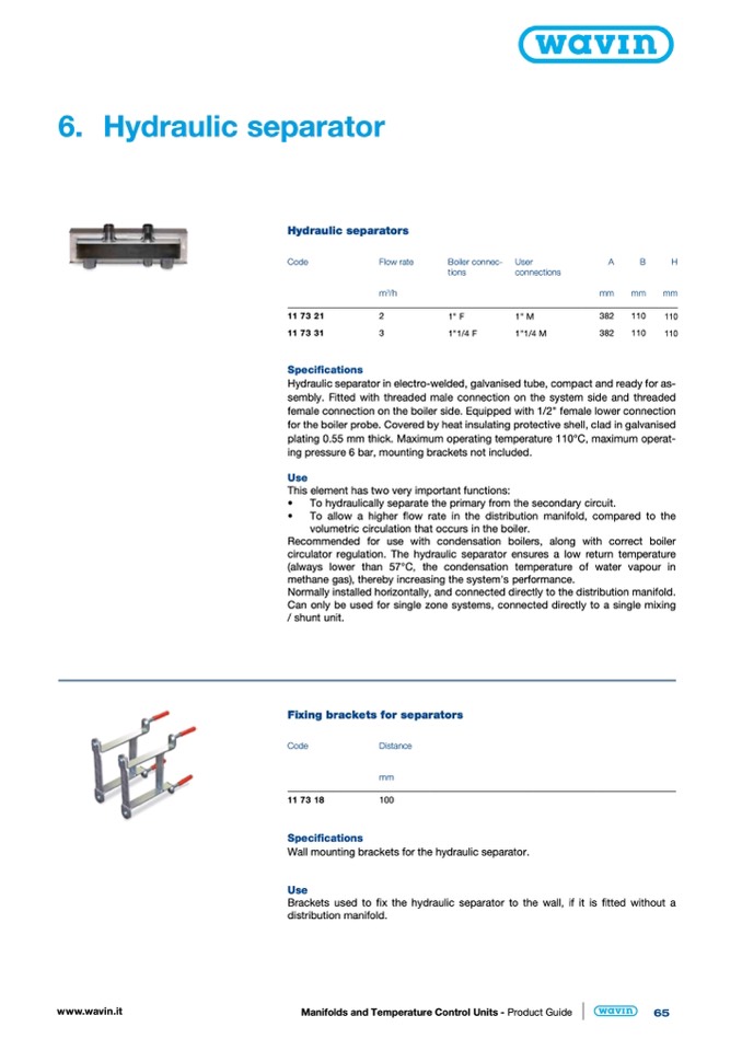
Hydraulic separator in electro-welded, galvanised tube, compact and ready for as-
sembly. Fitted with threaded male connection on the system side and threaded
female connection on the boiler side. Equipped with 1/2" female lower connection
for the boiler probe. Covered by heat insulating protective shell, clad in galvanised
plating 0.55 mm thick. Maximum operating temperature 110°C, maximum operat-
ing pressure 6 bar, mounting brackets not included.
Use
This element has two very important functions:
•
To hydraulically separate the primary from the secondary circuit.
•
To allow a higher flow rate in the distribution manifold, compared to the
volumetric circulation that occurs in the boiler.
Recommended for use with condensation boilers, along with correct boiler
circulator regulation. The hydraulic separator ensures a low return temperature
(always lower than 57°C, the condensation temperature of water vapour in
methane gas), thereby increasing the system's performance.
Normally installed horizontally, and connected directly to the distribution manifold.
Can only be used for single zone systems, connected directly to a single mixing
/ shunt unit.
Fixing brackets for separators
Code
Distance
mm
11 73 18
100
Specifications
Wall mounting brackets for the hydraulic separator.
Use
Brackets used to fix the hydraulic separator to the wall, if it is fitted without a
distribution manifold.
www.wavin.it
Manifolds and Temperature Control Units - Product Guide
65

