A
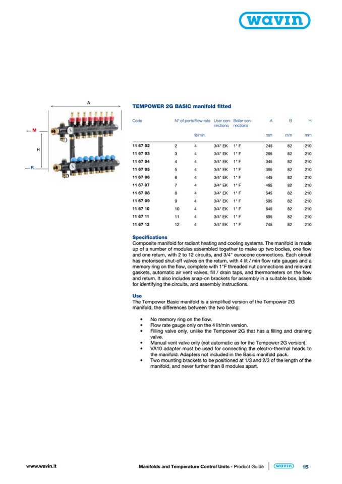
TEMPOWER 2G BASIC manifold fitted
M
H
R
Code
N° of ports
116702
2
116703
3
116704
4
116705
5
116706
6
116707
7
116708
8
116709
9
116710
10
116711
11
116712
12
Specifications
Flow rate
lit/min
4
4
4
4
4
4
4
4
4
4
4
User con- Boiler con-
nections nections
A
B
H
mm
mm
mm
245
82
210
295
82
210
345
82
210
395
82
210
445
82
210
495
82
210
545
82
210
595
82
210
645
82
210
695
82
210
745
82
210
3/4" EK
3/4" EK
3/4" EK
3/4" EK
3/4" EK
3/4" EK
3/4" EK
3/4" EK
3/4" EK
3/4" EK
3/4" EK
1" F
1" F
1" F
1" F
1" F
1" F
1" F
1" F
1" F
1" F
1" F
www.wavin.it
Manifolds and Temperature Control Units - Product Guide
15
Composite manifold for radiant heating and cooling systems. The manifold is made
up of a number of modules assembled together to make up two bodies, one flow
and one return, with 2 to 12 circuits, and 3/4" eurocone connections. Each circuit
has motorised shut-off valves on the return, with 4 lit / min flow rate gauges and a
memory ring on the flow, complete with 1"F threaded nut connections and relevant
gaskets, automatic air vent valves, fill / drain taps, and thermometers on the flow
and return. It also includes snap-on brackets for assembly in a suitable box, labels
for identifying the circuits, and assembly instructions.
Use
The Tempower Basic manifold is a simplified version of the Tempower 2G
manifold, the differences between the two being:
•
No memory ring on the flow.
•
Flow rate gauge only on the 4 lit/min version.
•
Filling valve only, unlike the Tempower 2G that has a filling and draining
valve.
•
Manual vent valve only (not automatic as for the Tempower 2G version).
•
VA10 adapter must be used for connecting the electro-thermal heads to
the manifold. Adapters not included in the Basic manifold pack.
•
Two mounting brackets to be positioned at 1/3 and 2/3 of the length of the
manifold, and never further than 8 modules apart.

