3.0 Product Suitability
The applications and tube type refered to in Table 3,
must be ahered to when using and connecting Conex
compression Brass and Copper Alloy fittings.
3.0.1 Drinking water installations
Drinking water installations must be planned and
installed in accordance with local and national water
byelaws and regulations and standards such as EN 806.
Conex compression fittings have several accreditations
for use with drinking water systems. For drinking
water applications it is important to select the correct
materials, EN 806 specifies requirements for drinking
water applications that must be adhered to. Conex
Compresion fittings are made from materials that fully
comply with European drinking water requirements. Conex
Compression is also certified by Bureau Veritas for marine
usage Ref. cert number . SMS.W.11./62847/D.0 and must
be used within the range of recognition of NR320.
3.0.2 Heating and cooling systems
In closed heating, cooling and chilled water systems, there
is generally an absence of oxygen which greatly reduces
the likelihood of corrosion. This means a range of metallic
materials may be used without the risk of corrosion; flow
direction does not need to be taken into consideration.
3.1 Thermal Expansion
3.1.1 Effects of expansion
The coefficient of linear expansion for copper is 16.8
x 10-6 °C. For example, a 10 m length of copper tube,
irrespective of its size, wall thickness or temper, will
increase in length by 10.8 mm temperature rise of 60
°C. Tubes installed on hot water services must be free to
accommodate this expansion; otherwise stresses will build
up in the pipework that may lead to joints being pulled
apart and/or tubes fracturing. Clearly the magnitude and
frequency of such changes in length will determine the life
of the joint or failure of the tube.
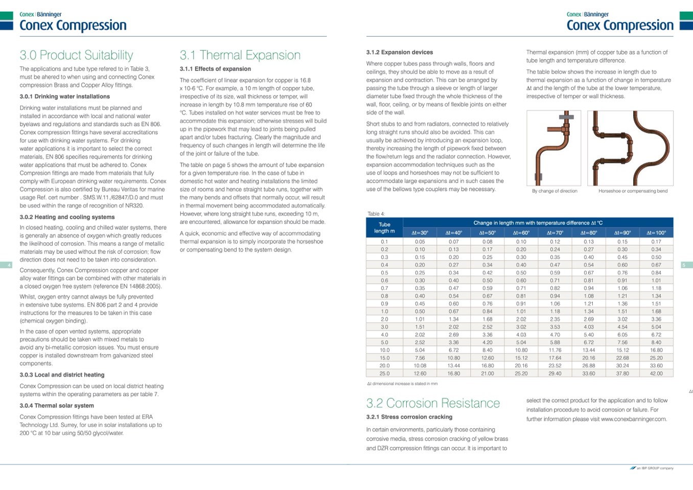
The table on page 5 shows the amount of tube expansion
for a given temperature rise. In the case of tube in
domestic hot water and heating installations the limited
size of rooms and hence straight tube runs, together with
the many bends and offsets that normally occur, will result
in thermal movement being accommodated automatically.
However, where long straight tube runs, exceeding 10 m,
are encountered, allowance for expansion should be made.
A quick, economic and effective way of accommodating
thermal expansion is to simply incorporate the horseshoe
or compensating bend to the system design.
3.1.2 Expansion devices
Where copper tubes pass through walls, floors and
ceilings, they should be able to move as a result of
expansion and contraction. This can be arranged by
passing the tube through a sleeve or length of larger
diameter tube fixed through the whole thickness of the
wall, floor, ceiling, or by means of flexible joints on either
side of the wall.
Short stubs to and from radiators, connected to relatively
long straight runs should also be avoided. This can
usually be achieved by introducing an expansion loop,
thereby increasing the length of pipework fixed between
the flow/return legs and the radiator connection. However,
expansion accommodation techniques such as the
use of loops and horseshoes may not be sufficient to
accommodate large expansions and in such cases the
use of the bellows type couplers may be necessary.
Thermal expansion (mm) of copper tube as a function of
tube length and temperature difference.
The table below shows the increase in length due to
thermal expansion as a function of change in temperature
∆t and the length of the tube at the lower temperature,
irrespective of temper or wall thickness.
Tube
length m
Change in length mm with temperature difference ∆t °C
∆t=30°
∆t=40°
∆t=50°
∆t=60°
∆t=70°
∆t=80°
∆t=90°
∆t=100°
0.2
0.10
0.13
0.17
0.20
0.24
0.27
0.30
0.34
0.4
0.20
0.27
0.34
0.40
0.47
0.54
0.60
0.67
4
5
Consequently, Conex Compression copper and copper
alloy water fittings can be combined with other materials in
a closed oxygen free system (reference EN 14868:2005).
Whilst, oxygen entry cannot always be fully prevented
in extensive tube systems. EN 806 part 2 and 4 provide
instructions for the measures to be taken in this case
(chemical oxygen binding).
In the case of open vented systems, appropriate
precautions should be taken with mixed metals to
avoid any bi-metallic corrosion issues. You must ensure
copper is installed downstream from galvanized steel
components.
3.0.3 Local and district heating
Conex Compression can be used on local district heating
systems within the operating parameters as per table 7.
3.0.4 Thermal solar system
Conex Compression fittings have been tested at ERA
Technology Ltd. Surrey, for use in solar installations up to
200 °C at 10 bar using 50/50 glycol/water.
Table 4:
0.1
0.05
0.3
0.15
0.07
0.08
0.20
0.25
By change of direction
0.10
0.12
0.30
0.35
Horseshoe or compensating bend
0.13
0.15
0.17
0.40
0.45
0.50
0.5
0.25
0.34
0.7
0.35
0.47
0.9
0.45
0.60
2.0
1.01
1.34
4.0
2.02
2.69
10.0
5.04
6.72
20.0
10.08
13.44
t dimensional increase is stated in mm
3.2 Corrosion Resistance
3.2.1 Stress corrosion cracking
In certain environments, particularly those containing
corrosive media, stress corrosion cracking of yellow brass
and DZR compression fittings can occur. It is important to
0.42
0.50
0.59
0.71
0.76
0.91
1.68
2.02
3.36
4.03
8.40
10.80
16.80
20.16
0.59
0.67
0.82
0.94
1.06
1.21
2.35
2.69
4.70
5.40
11.76
13.44
23.52
26.88
0.76
0.84
1.06
1.18
1.36
1.51
3.02
3.36
6.05
6.72
15.12
16.80
30.24
33.60
0.6
0.30
0.40
0.50
0.60
0.71
0.81
0.91
1.01
0.8
0.40
0.54
0.67
0.81
0.94
1.08
1.21
1.34
1.0
0.50
0.67
0.84
1.01
1.18
1.34
1.51
1.68
3.0
1.51
2.02
2.52
3.02
3.53
4.03
4.54
5.04
5.0
2.52
3.36
4.20
5.04
5.88
6.72
7.56
8.40
15.0
7.56
10.80
12.60
15.12
17.64
20.16
22.68
25.20
25.0
12.60
16.80
21.00
25.20
29.40
33.60
37.80
42.00
select the correct product for the application and to follow
installation procedure to avoid corrosion or failure. For
further information please visit www.conexbanninger.com.
t

