434
www.brandonivalves.it
- Non montare il giunto direttamente a contatto con superfici
in gomma (es. con valvole a farfalla).
- Non montare guarnizioni tra il giunto e la controflangia.
- Evitare l’esposizione diretta alla luce del sole. In caso di
montaggio all’esterno predisporre adeguati ripari e prote-
zioni se necessario.
MANUTENZIONE
- Non è richiesta manutenzione.
INSTALLAZIONE DEI LIMITATORI DI ALLUNGAMENTO
Composizione del kit
COMPONENTE - COMPONENT
ASTE - RODS
- Do not install the joint in direct contact with a rubber surface
(for example, butterfly valves).
- Do not place gaskets between the joint and counter flange.
- Avoid exposure to direct sunlight. In the case of installing out-
side, protect the joint,
if necessary.
MAINTENANCE
The valve does not require maintenance.
INSTALLATION OF THE CONTROL ROD UNIT
The kit consists of:
PIASTRE - PLATE
DADI - HEX NUTS
4
8
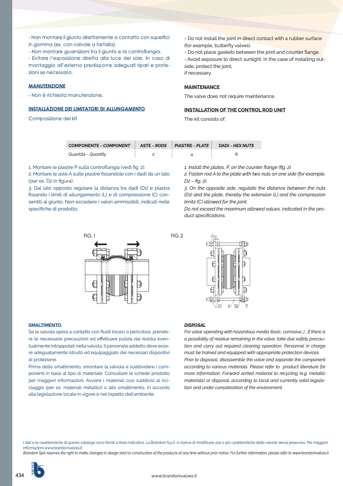
1. Install the plates, P, on the counter flange (fig. 2)
2. Fasten rod A to the plate with two nuts on one side (for example,
D2 – fig. 2).
3. On the opposite side, regulate the distance between the nuts
(D1) and the plate, thereby the extension (L) and the compression
limits (C) allowed for the joint.
Do not exceed the maximum allowed values, indicated in the pro-
duct specifications.
L
C
Quantità - Quantity
2
1. Montare le piastre P sulla contro
flangia (vedi fig. 2).
2. Montare le aste A sulle piastre fissandole con i dadi da un lato
(per es. D2 in figura).
3. Dal lato opposto regolare la distanza tra dadi (D1) e piastra
fissando i limiti di allungamento (L) e di compressione (C) con-
sentiti al giunto. Non eccedere i valori ammissibili, indicati nelle
specifiche di prodotto.
FIG. 1
FIG. 2
SMALTIMENTO
Se la valvola opera a contatto con fluidi tossici o pericolosi, prende-
re le necessarie precauzioni ed effettuare pulizia dai residui even-
tualmente intrappolati nella valvola. Il personale addetto deve esse-
re adeguatamente istruito ed equipaggiato dei necessari dispositivi
di protezione.
Prima dello smaltimento, smontare la valvola e suddividere i com-
ponenti in base al tipo di materiale. Consultare le schede prodotto
per maggiori informazioni. Avviare i materiali così suddivisi al rici-
claggio (per es. materiali metallici) o allo smaltimento, in accordo
alla legislazione locale in vigore e nel rispetto dell’ambiente.
DISPOSAL
I dati e le caratteristiche di questo catalogo sono forniti a titolo indicativo. La Brandoni S.p.A. si riserva di modificare una o più caratteristiche delle valvole senza preavviso. Per maggiori
informazioni www.brandonivalves.it.
Brandoni SpA reserves the right to make changes in design and/or construction of the products at any time without prior notice. For further information, please refer to www.brandonivalves.it
D1
A D2
P
For valve operating with hazardous media (toxic, corrosive...) , if there is
a possibility of residue remaining in the valve, take due safety precau-
tion and carry out required cleaning operation. Personnel in charge
must be trained and equipped with appropriate protection devices.
Prior to disposal, disassemble the valve and separate the component
according to various materials. Please refer to product literature for
more information. Forward sorted material to recycling (e.g. metallic
materials) or disposal, according to local and currently valid legisla-
tion and under consideration of the environment.
V
A
L
V
E
S

