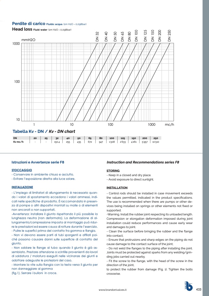
Perdite di carico
Fluido: acqua (1m H2O = 0,098bar)
Head loss
Fluid: water (1m H2O = 0,098bar)
mmH2O
1000
100
10
1
10
100
1000
mc/h
Tabella Kv - DN / Kv - DN chart
DN
20
25
32
40
50
65
80
100
125
150
200
250
Kv mc/h
-
-
150,4
255
435
672
947
1
.
508
2
.
633
4
.
261
5
.
957
10
.
510
Istruzioni e Avvertenze serie F8
STOCCAGGIO
- Conservare in ambiente chiuso e asciutto.
- Evitare l’esposizione diretta alla luce solare.
INSTALLAZIONE
- L’impiego di limitatori di allungamento è necessario quan-
do i valori di spostamento eccedono i valori ammessi, indi-
cati nelle specifiche di prodotto. É raccomandato in presen-
za di pompe o altri dispositivi montati su molle o di elementi
non ancorati o non supportati.
-Avvertenza: installare il giunto rispettando il più possibile la
lunghezza neutra (non deformato). La deformazione di al-
lungamento/compressione imposta al montaggio può ridur-
re le prestazioni ed essere causa di rotture durante l’esercizio.
- Pulire le superfici prima del contatto fra gomma e flangia.
- Non vi devono essere parti di tubi sporgenti e affilati poi-
ché possono causare danni sulle superficie di contatto del
giunto.
- Non saldare le flange al tubo quando il giunto è già as-
semblato. Prestare attenzione a scintille provenienti da lavori
di saldatura / molatura eseguiti nelle vicinanze dei giunti e
adottare adeguate le protezioni del caso.
- Montare la vite sulla flangia con la testa verso il giunto per
non danneggiare al gomma
(fig.1). Serrare i bulloni in croce.
●
Instruction and Recommendations series F8
STORING
- Keep in a closed and dry place.
- Avoid exposure to direct sunlight.
INSTALLATION
- Control rods should be installed in case movement exceeds
the values permitted, indicated in the product specifications.
The use is recommended when there are pumps or other de-
vices being installed on springs or other elements not fixed or
supported.
-Warning. Install the rubber joint respecting its unloaded length.
Compression or elongation deformation imposed during joint
installation could reduce performances and cause early wear
and damages to joint.
- Clean the surface before bringing the rubber and the flange
into contact;
- Ensure that protrusions and sharp edges on the piping do not
cause damage to the contact surface of the joint;
- Do not weld the flanges to the piping after installing the joint.
Joints must be protected against sparks from any welding/grin-
ding jobs carried out nearby.
- Fit the screw to the flange, with the head of the screw in the
direction of the joint,
to protect the rubber from damage (Fig. 1). Tighten the bolts
crosswise.
www.brandonivalves.it
433
V
A
L
V
E
S
D
N
3
2
D
N
4
0
D
N
5
0
D
N
6
5
D
N
8
0
D
N
1
0
0
D
N
1
2
5
D
N
1
5
0
D
N
2
0
0
D
N
2
5
0

