GRUPPI IDRAULICI PER GENERATORI DI CALORE / HYDRAULIC GROUPS FOR HEAT GENERATORS
Dati tecnici
Technical data
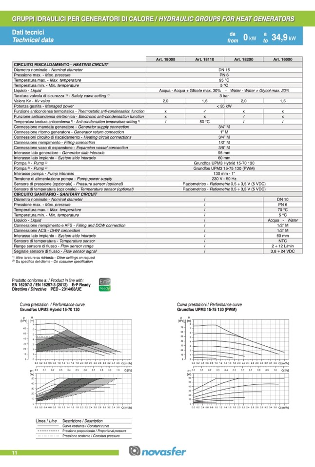
CIRCUITO RISCALDAMENTO - HEATING CIRCUIT
Diametro nominale - Nominal diameter
Pressione max. - Max. pressure
Temperatura max. - Max. temperature
Temperatura min. - Min. temperature
Liquido - Liquid
Taratura valvola di sicurezza
1)
- Safety valve setting
1)
Valore Kv - Kv value
Potenza gestita - Managed power
Funzione anticondensa termostatica - Thermostatic anti-condensation function
Funzione anticondensa elettronica - Electronic anti-condensation function
Temperatura taratura anticondensa
1)
- Anti-condensation temperature setting
1)
Connessione mandata generatore - Generator supply connection
Connessione ritorno generatore - Generator return connection
Connessioni circuito di riscaldamento - Heating circuit connections
Connessione riempimento - Filling connection
Connessione vaso di espansione - Expansion vessel connection
Interasse lato generatore - Generator side interaxis
Interasse lato impianto - System side interaxis
Pompa
2)
- Pump
2)
Pompa
2)
- Pump
2)
Interasse pompa - Pump interaxis
Tensione di alimentazione pompa - Pump power supply
Sensore di pressione (opzionale) - Pressure sensor (optional)
Sensore di temperatura (opzionale) - Temperature sensor (optional)
CIRCUITO SANITARIO - SANITARY CIRCUIT
Diametro nominale - Nominal diameter
Pressione max. - Max. pressure
Temperatura max. - Max. temperature
Temperatura min. - Min. temperature
Liquido - Liquid
Connessione riempimento e AFS - Filling and DCW connection
Connessione ACS - DHW connection
Interasse lato impianto - System side interaxis
Sensore di temperatura - Temperature sensor
Range sensore di flusso - Flow sensor range
Segnale sensore di flusso - Flow sensor signal
1)
Altre tarature su richiesta - Other settings on request
2)
Su specifica del cliente - On costumer specification
Prodotto conforme a: / Product in line with:
EN 16297-2 / EN 16297-3 (2012) ErP Ready
Direttiva / Directive PED - 2014/68/UE
Curva prestazioni / Performance curve
Grundfos UPM3 Hybrid 15-70 130
da
0
kW
a
34,9
kW
11
p
H
p
H
[kPa] [m]
[kPa] [m]
7
8
70
7
60
6
60
50
5
40
4
30
3
20
2
10
50
40
30
3
20
2
10
1
0
0
P1
[W]
50
40
30
20
10
6
5
4
0.0 0.2 0.4 0.6 0.8 1.0 1.2 1.4 1.6 1.8 2.0 2.2 2.4 2.6 2.8 3.0 3.2 3.4 3.6 Q [m3/h]
0.0 0.2 0.4 0.6 0.8 1.0 1.2 1.4 1.6 1.8 2.0 2.2 2.4 2.6 2.8 3.0 3.2 3.4 3.6 Q [m3/h]
0.0
0.1
0.2
0.3
0.4
0.5
0.6
0.7
0.8
0.9
1.0
Q [l/s]
P1 0.0
[W]
0.1
0.2
0.3
0.4
0.5
0.6
0.7
0.8
0.9
1.0
Q [l/s]
0
0
0.0 0.2 0.4 0.6 0.8 1.0 1.2 1.4 1.6 1.8 2.0 2.2 2.4 2.6 2.8 3.0 3.2 3.4 3.6 Q [m3/h]
Linea / Line Descrizione / Description
Curva costante / Constant curve
Pressione proporzionale / Proportional pressure
Pressione costante / Constant pressure
0.0 0.2 0.4 0.6 0.8 1.0 1.2 1.4 1.6 1.8 2.0 2.2 2.4 2.6 2.8 3.0 3.2 3.4 3.6 Q [m3/h]
Art. 18000
Art. 18110
Art. 18200
Art. 16000
Acqua - Acqua + Glicole max. 30% -
2,0
x
x
/
1,6
✓
x
50 °C
3 bar
< 35 kW
2,0
x
✓
/
1,5
x
x
/
1
0
0
60
50
40
30
20
10
DN 15
PN 6
95 °C
5 °C
Water - Water + Glycol max. 30%
3/4” M
1” M
3/4” M
1/2” M
3/8” M
95 mm
60 mm
Grundfos UPM3 Hybrid 15-70 130
Grundfos UPM3 15-75 130 (PWM)
130 mm - 1”
230 V - 50 Hz
Raziometrico - Ratiometric 0,5 ÷ 3,5 V (5 VDC)
Raziometrico - Ratiometric 0,5 ÷ 3,5 V (5 VDC)
/
/
/
/
/
/
/
/
/
/
/
Curva prestazioni / Performance curve
Grundfos UPM3 15-75 130 (PWM)
DN 10
PN 6
70 °C
5 °C
Acqua - Water
1/2” M
1/2” M
60 mm
NTC
2 ÷ 12 L/min
3,8 ÷ 24 VDC
da
a
from
17
ktWo
from
to
47
kW

