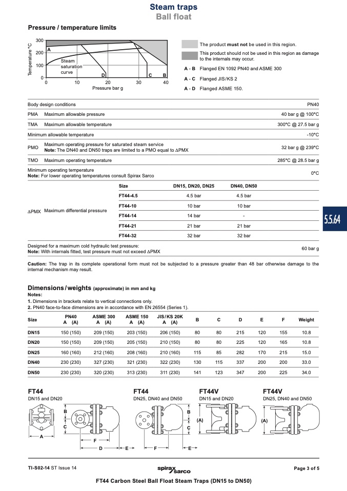
Pressure / temperature limits
������
������
A
������
�
�
curv
e
D
C
B
��
����
����
����
����
Pressure bar g
Body design conditions
PMA Maximum allowable pressure
TMA Maximum allowable temperature
Minimum allowable temperature
The product must not be used in this region.
This product should not be used in this region as damage
to the internals may occur.
Flanged EN 1092 PN40 and ASME 300
Flanged JIS/KS 2
Flanged ASME 150.
PN40
40 bar g @ 100°C
300°C @ 27.5 bar g
-10°C
32 bar g @ 239°C
285°C @ 28.5 bar g
0°C
5.5.64
60 bar g
Steam
saturation
A-B
A-C
A - D
PMO
Maximum operating pressure for saturated steam service
Note: The DN40 and DN50 traps are limited to a PMO equal to DPMX
TMO Maximum operating temperature
Minimum operating temperature
Note: For lower operating temperatures consult Spirax Sarco
Size
DPMX Maximum differential pressure
FT44-4.5
FT44-10
FT44-14
FT44-21
FT44-32
DN15, DN20, DN25
4.5 bar
10 bar
14 bar
21 bar
32 bar
DN40, DN50
4.5 bar
10 bar
-
21 bar
32 bar
Designed for a maximum cold hydraulic test pressure:
Note: With internals fitted, test pressure must not exceed DPMX
Steam traps
Ball float
T
e
m
p
e
r
a
t
u
r
e
°
C
Caution: The trap in its complete operational form must not be subjected to a pressure greater than 48 bar otherwise damage to the
internal mechanism may result.
Dimensions/weights (approximate) in mm and kg
Notes:
1. Dimensions in brackets relate to vertical connections only.
2. PN40 face-to-face dimensions are in accordance with EN 26554 (Series 1).
Size
DN15
DN20
DN25
DN40
DN50
FT44
DN15 and DN20
B
C
D
80
80
215
80
80
225
115
85
282
130
115
337
141
123
347
FT44V
DN15 and DN20
(A)
E
F
Weight
C
A
F
C
D
E
F
E
TI-S02-14 ST Issue 14
Page 3 of 5
PN40
A (A)
150 (150)
150 (150)
160 (160)
230 (230)
230 (230)
ASME 300
A (A)
209 (150)
209 (150)
212 (160)
327 (230)
320 (230)
ASME 150
A (A)
203 (150)
205 (150)
208 (160)
321 (230)
313 (230)
FT44
JIS/KS 20K
A (A)
206 (150)
210 (150)
210 (160)
322 (230)
311 (230)
B
B
DN25, DN40 and DN50
120
155
10.8
120
165
10.8
170
215
15.0
200
200
33.0
200
225
34.0
FT44V
DN25, DN40 and DN50
(A)
FT44 Carbon Steel Ball Float Steam Traps (DN15 to DN50)

