Boiler house
Level controls
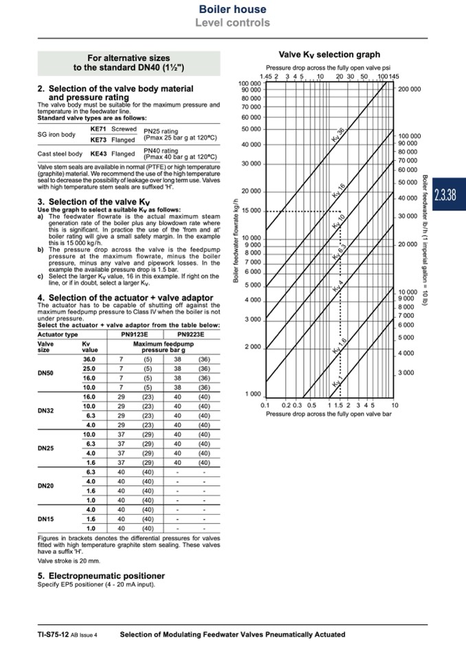
Valve Kv selection graph
Pressure drop across the fully open valve psi
1.45
2
345
10
20305
0
100145
For alternative sizes
to the standard DN40 (11⁄2")
2. Selection of the valve body material
100 000
90 000
80 000
70 000
60 000
50 000
40 000
30 000
20 000
15 000
10 000
9 000
8 000
7 000
6 000
5 000
4 000
3 000
2 000
200 000
100 000
90 000
80 000
70 000
60 000
50 000
40 000
30 000
20 000
10 000
9 000
8 000
7 000
6 000
5 000
4 000
3 000
and pressure rating
The valve body must be suitable for the maximum pressure and
temperature in the feedwater line.
Standard valve types are as follows:
SG iron body
Cast steel body
KE71 Screwed
KE73 Flanged
KE43 Flanged
PN25 rating
(Pmax 25 bar g at 120oC)
PN40 rating
(Pmax 40 bar g at 120oC)
Valve stem seals are available in normal (PTFE) or high temperature
(graphite) material. We recommend the use of the high temperature
seal to decrease the possibility of leakage over long term use. Valves
with high temperature stem seals are suffixed 'H'.
3. Selection of the valve Kv
Use the graph to select a suitable Kv as follows:
a) The feedwater flowrate is the actual maximum steam
generation rate of the boiler plus any blowdown rate where
this is significant. In practice the use of the 'from and at'
boiler rating will give a small safety margin. In the example
this is 15 000 kg/h.
b) The pressure drop across the valve is the feedpump
pressure at the maximum flowrate, minus the boiler
pressure, minus any valve and pipework losses. In the
example the available pressure drop is 1.5 bar.
c) Select the larger Kv value, 16 in this example. If right on the
line, or if in doubt, select a larger Kv.
4. Selection of the actuator + valve adaptor
The actuator has to be capable of shutting off against the
maximum feedpump pressure to Class IV when the boiler is not
under pressure.
Select the actuator + valve adaptor from the table below:
Actuator type
Valve
Kv
size
value
PN9223E
Maximum feedpump
pressure bar g
PN9123E
7
(5)
7
(5)
7
(5)
7
(5)
29
(23)
29
(23)
29
(23)
29
(23)
37
(29)
37
(29)
37
(29)
37
(29)
40
(40)
40
(40)
40
(40)
40
(40)
40
(40)
40
(40)
40
(40)
36.0
38
(36)
DN50
25.0
38
(36)
16.0
38
(36)
10.0
38
(36)
16.0
40
(40)
10.0
40
(40)
6.3
40
(40)
4.0
40
(40)
10.0
40
(40)
6.3
40
(40)
4.0
40
(40)
1.6
40
(40)
6.3
-
-
4.0
-
-
1.6
-
-
1.0
-
-
4.0
-
-
DN15
1.6
1.0
-
-
Figures in brackets denotes the differential pressures for valves
fitted with high temperature graphite stem sealing. These valves
have a suffix 'H'.
Valve stroke is 20 mm.
5. Electropneumatic positioner
Specify EP5 positioner (4 - 20 mA input).
1 000
Pressure drop across the fully open valve bar
DN32
DN25
DN20
0.1
0.2 0.3 0.5
1 1.5 2 3 4 5
10
-
-
TI-S75-12 AB Issue 4
Selection of Modulating Feedwater Valves Pneumatically Actuated
2.3.38
B
o
i
l
e
r
f
e
e
d
w
a
t
e
r
l
b
/
h
(
1
i
m
p
e
r
i
a
l
g
a
l
l
o
n
=
1
0
l
b
)
B
o
i
l
e
r
f
e
e
d
w
a
t
e
r
f
l
o
w
r
a
t
e
k
g
/
h
K
v
1
.
6
K
v
1
K
v
6
.
3
K
v
4

