Steam traps
Ball float
ISO 9001
���
��
��
��
��
��
5.5.37
0.5
1 2 3
4.5 7 10
70
140
250
380
560
870
1130
120
240
360
500
640
920
1 220
TI-S02-28
ST Issue 4
Cert. No. LRQ 0963008
Capacity Charts for
FT14, FT14HC, FTGS14 and
� ���
� ���
FTGS14HC Ball Float Steam Traps
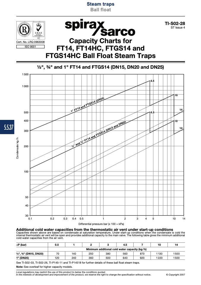
1⁄2", 3⁄4" and 1" FT14 and FTGS14 (DN15, DN20 and DN25)
��
�
�
���
���
���
���
��
��
��
��
��
���
���
���
��� ���
�
�
�
�
�
Differential pressure bar (x 100 = kPa)
Additional cold water capacities from the thermostatic air vent under start-up conditions
Capacities shown above are based on condensate at saturation temperature. Under start-up conditions when the condensate is cold the
internal thermostatic air vent will be open and provides additional capacity to the main valve. The following table gives the minimum additional
cold water capacities from the air vent.
∆P (bar)
14
1500
1500
© Copyright 2007
Minimum additional cold water capacity (kg/h)
1⁄2", 3⁄4" (DN15, DN20)
1" (DN25)
See TI-S02-03, TI-S02-26, TI-P145-11 and TI-P14518 for further details of these ball float steam traps.
Note: See overleaf for higher capacity models.
Local regulations may restrict the use of this product to below the conditions quoted.
In the interests of development and improvement of the product, we reserve the right to change the specification without notice.
�������������������������
�����������������������������������������
C
o
n
d
e
n
s
a
t
e
k
g
/
h

