Boiler house
Level controls
38.3
40.0 (40.0)
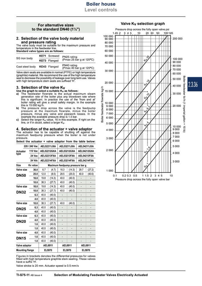
Valve Kv selection graph
Pressure drop across the fully open valve psi
1.45
2
345
10
20305
0
100145
For alternative sizes
to the standard DN40 (11⁄2")
2. Selection of the valve body material
100 000
90 000
80 000
70 000
60 000
50 000
40 000
30 000
20 000
15 000
10 000
9 000
8 000
7 000
6 000
5 000
4 000
3 000
2 000
1 000
200 000
100 000
90 000
80 000
70 000
60 000
50 000
40 000
30 000
20 000
10 000
9 000
8 000
7 000
6 000
5 000
4 000
3 000
and pressure rating
The valve body must be suitable for the maximum pressure and
temperature in the feedwater line.
Standard valve types are as follows:
SG iron body
Cast steel body
KE71 Screwed
KE73 Flanged
KE43 Flanged
PN25 rating
(Pmax 25 bar g at 120oC)
PN40 rating
(Pmax 40 bar g at 120oC)
Valve stem seals are available in normal (PTFE) or high temperature
(graphite) material. We recommend the use of the high temperature
seal to decrease the possibility of leakage over long term use. Valves
with high temperature stem seals are suffixed 'H'.
3. Selection of the valve Kv
Use the graph to select a suitable Kv as follows:
a) The feedwater flowrate is the actual maximum steam
generation rate of the boiler plus any blowdown rate where
this is significant. In practice the use of the 'from and at'
boiler rating will give a small safety margin. In the example
this is 15 000 kg/h.
b) The pressure drop across the valve is the feedpump
pressure at the maximum flowrate, minus the boiler
pressure, minus any valve and pipework losses. In the
example the available pressure drop is 1.5 bar.
c) Select the larger Kv value, 16 in this example. If right on the
line, or if in doubt, select a larger Kv.
4. Selection of the actuator + valve adaptor
The actuator has to be capable of shutting off against the
maximum feedpump pressure when the boiler is not under
pressure.
Select the actuator + valve adaptor from the table below:
AEL52211JXA AEL53211JXA
AEL52212GXA AEL53212GXA
AEL52213FXA AEL53213FXA
AEL52214FXA AEL53214FXA
220 / 240 Vac
AEL54211JXA
AEL54212GXA
AEL54213FXA
AEL54214FXA
Actuator
type
Size
Valve size
DN50
Valve size
DN32
Valve size
DN25
Valve size
DN20
Valve size
DN15
Valve adaptor
36.0
25.0
16.0
10.0
16.0
10.0
6.3
4.0
10.0
6.3
4.0
6.3
4.0
1.6
1.0
4.0
1.6
1.0
Maximum feedpump pressure bar g
29.7
40.0
(27.2)
(40.0)
0.1
0.2 0.3 0.5
Pressure drop across the fully open valve bar
110 Vac
24 Vac
24 Vdc
Kv value
6.7
(4.7)
16.3 (14.3)
12.0
(8.5)
28.5 (25.0)
1 1.5 2 3 4 5
10
-
-
-
-
-
-
-
-
-
-
-
-
-
-
-
-
-
-
-
-
-
-
-
-
-
-
-
-
-
-
-
-
19.8
(14.3)
40.0 (40.0)
(27.7)
19.8
(14.3)
40.0 (40.0)
38.3
(27.7)
40.0 (40.0)
40.0
(40.0)
-
-
40.0
(40.0)
-
-
38.3
(27.7)
40.0 (40.0)
40.0
(40.0)
-
-
40.0
(40.0)
-
-
40.0
(40.0)
-
-
40.0
(40.0)
-
-
40.0
(40.0)
-
-
40.0
(40.0)
-
-
40.0
(40.0)
-
-
40.0
(40.0)
-
-
40.0
(40.0)
-
-
AEL6911
AEL6911
Mounting flange
AEL6911
EL5970
EL5970
EL5970
Figures in brackets denotes the differential pressures for valves
fitted with high temperature graphite stem sealing. These valves
have a suffix 'H'.
Valve stroke is 20 mm. Actuator speed is 0.5 mm/s
TI-S75-11 AB Issue 4
Selection of Modulating Feedwater Valves Electrically Actuated
2.3.36
B
o
i
l
e
r
f
e
e
d
w
a
t
e
r
l
b
/
h
(
1
i
m
p
e
r
i
a
l
g
a
l
l
o
n
=
1
0
l
b
)
B
o
i
l
e
r
f
e
e
d
w
a
t
e
r
f
l
o
w
r
a
t
e
k
g
/
h
K
v
1
.
6
K
v
1
K
v
6
.
3
K
v
4

