Steam traps
FT14
Ball Float Steam Trap
(Flanged)
Ball float
Local regulations may restrict the use of this product to below the conditions quoted.
In the interests of development and improvement of the product, we reserve the right to change the specification without notice.
© Copyright 2013
TI-S02-26
ST Issue 8
Description
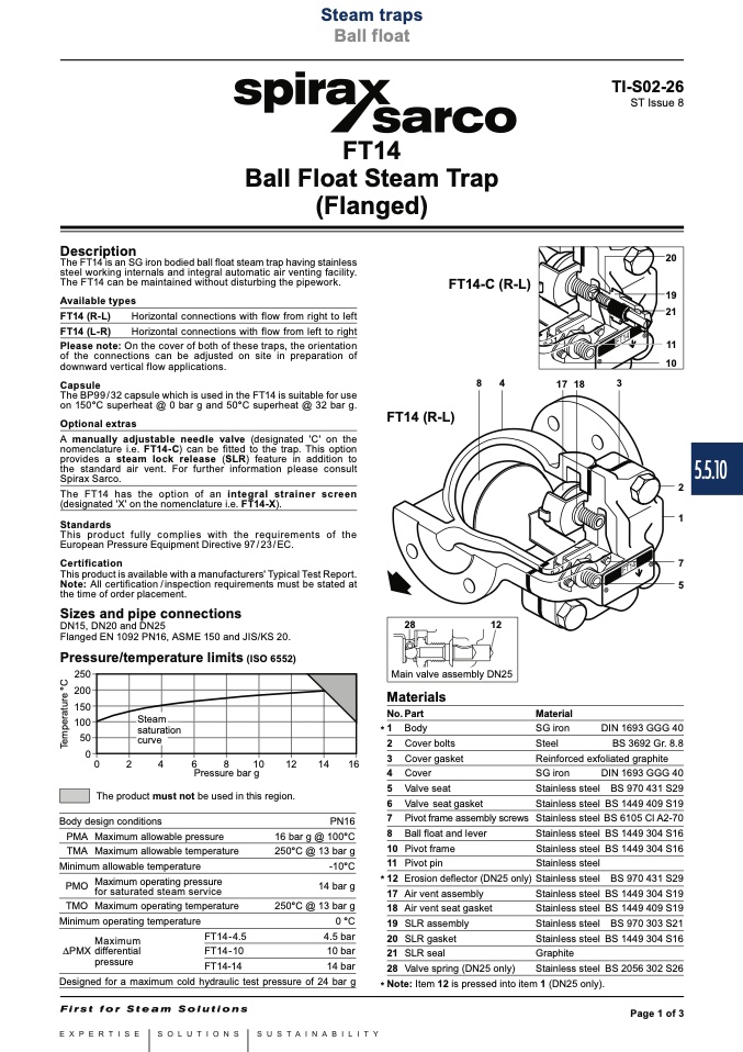
The FT14 is an SG iron bodied ball float steam trap having stainless
steel working internals and integral automatic air venting facility.
The FT14 can be maintained without disturbing the pipework.
Available types
FT14 (R-L)
Horizontal connections with flow from right to left
FT14 (L-R)
Horizontal connections with flow from left to right
Please note: On the cover of both of these traps, the orientation
of the connections can be adjusted on site in preparation of
downward vertical flow applications.
The BP99 / 32 capsule which is used in the FT14 is suitable for use
on 150°C superheat @ 0 bar g and 50°C superheat @ 32 bar g.
Optional extras
A manually adjustable needle valve (designated 'C' on the
nomenclature i.e. FT14-C) can be fitted to the trap. This option
provides a steam lock release (SLR) feature in addition to
the standard air vent. For further information please consult
Spirax Sarco.
The FT14 has the option of an integral strainer screen
(designated 'X' on the nomenclature i.e. FT14-X).
This product fully complies with the requirements of the
European Pressure Equipment Directive 97/23/EC.
This product is available with a manufacturers' Typical Test Report.
Note: All certification / inspection requirements must be stated at
the time of order placement.
Sizes and pipe connections
DN15, DN20 and DN25
Flanged EN 1092 PN16, ASME 150 and JIS/KS 20.
Pressure/temperature limits (ISO 6552)
FT14-C (R-L)
20
19
21
11
10
Capsule
8
4
171
8
3
FT14 (R-L)
Standards
2
1
7
5
Certification
28
12
Main valve assembly DN25
������
������
������
������
����
��
Materials
No. Part
* 1 Body
2 Cover bolts
Material
SG iron
Steel
Reinforced exfoliated graphite
Steam
saturation
DIN 1693 GGG 40
BS 3692 Gr. 8.8
curve
3 Cover gasket
Pressure bar g
4 Cover
��
��
��
��
��
����
����
����
����
SG iron
Stainless steel
Stainless steel
Stainless steel
Stainless steel
Stainless steel
Stainless steel
Stainless steel
Stainless steel
Stainless steel
Stainless steel
Stainless steel
Graphite
Stainless steel
DIN 1693 GGG 40
BS 970 431 S29
BS 1449 409 S19
BS 6105 Cl A2-70
BS 1449 304 S16
BS 1449 304 S16
BS 970 431 S29
BS 1449 304 S19
BS 1449 409 S19
BS 970 303 S21
BS 1449 304 S16
BS 2056 302 S26
The product must not be used in this region.
5 Valve seat
6 Valve seat gasket
7 Pivot frame assembly screws
8 Ball float and lever
10 Pivot frame
11 Pivot pin
* 12 Erosion deflector (DN25 only)
17 Air vent assembly
18 Air vent seat gasket
19 SLR assembly
20 SLR gasket
21 SLR seal
28 Valve spring (DN25 only)
Body design conditions
PMA Maximum allowable pressure
TMA Maximum allowable temperature
Minimum allowable temperature
PMO
Maximum operating pressure
for saturated steam service
250°C @ 13 bar g
0 °C
4.5 bar
10 bar
14 bar
Designed for a maximum cold hydraulic test pressure of 24 bar g
PN16
16 bar g @ 100°C
250°C @ 13 bar g
-10°C
14 bar g
TMO Maximum operating temperature
Minimum operating temperature
Maximum
PMX differential
FT14-4.5
FT14-10
FT14-14
pressure
* Note: Item 12 is pressed into item 1 (DN25 only).
Page 1 of 3
5.5.10
T
e
m
p
e
r
a
t
u
r
e
°
C

