Steam traps
Balanced pressure
5.2.25
ISO 9001
Steam
saturat
curve
ion
TI-P124-08
ST Issue 2
Cert. No. LRQ 0963008
BPM21L
Carbon Steel
Balanced Pressure Thermostatic Steam Trap
Description
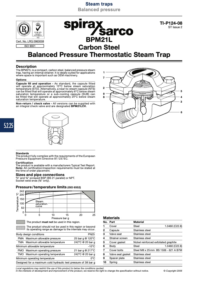
The BPM21L is a compact, carbon steel, balanced pressure steam
trap, having an internal strainer. It is ideally suited for applications
where space is important such as OEM machinery.
1
7
Options
Capsule fill and operation - As standard, the capsule fitted
will operate at approximately 13°C below steam saturation
temperature (STD). Alternatively, a near-to-steam capsule (NTS)
can be fitted that will operate at approximately 6°C below steam
saturation temperature or a sub-cooling capsule (SUB) can
9
be fitted that will operate at approximately 24°C below steam
8
saturation temperature.
Non-return / check valve - All versions can be supplied with
an integral check valve and are designated BPM21LCV.
2
5
4
3
6
Standards
The product fully complies with the requirements of the European
Pressure Equipment Directive 97 / 23 / EC.
Certification
The product is available with a manufacturers Typical Test Report.
Note: All certification/inspection requirements must be stated at
the time of order placement.
Sizes and pipe connections
" and 1⁄2" screwed BSP (BS 21 parallel) or NPT.
Socket weld ends (1⁄2" only).
Pressure / temperature limits (ISO 6552)
���
���
���
���
��
�
�
�
��
��
��
��
Pressure bar g
Materials
The product must not be used in this region.
No. Part
Material
Steel
Stainless steel
Stainless steel
Stainless steel
Nickel reinforced exfoliated graphite
Steel
1.0460 (C22.8)
Steel M8 x 25mm BS 1506 - 621 A B7M
Stainless steel
Stainless steel
Stainless steel
Local regulations may restrict the use of this product to below the conditions quoted.
In the interests of development and improvement of the product, we reserve the right to change the specification without notice.
© Copyright 2006
The product should not be used in this region or beyond
its operating range as damage to the internals may occur.
1.0460 (C22.8)
1
Cover
Body design conditions
PMA Maximum allowable pressure
TMA Maximum allowable temperature
Minimum allowable temperature
PMO Maximum operating pressure
TMO Maximum operating temperature
2
Capsule
PN25
3
Valve seat
25 bar g @ 120°C
4
Strainer screen
242°C @ 20 bar g
5
Cover gasket
-10°C
6
Body
21 bar g @ 217°C
7
Cover bolts
242°C @ 20 bar g
8
Valve seat gasket
0°C
9
Spacer plate
Minimum operating temperature
Designed for a maximum cold hydraulic test pressure of 38 bar g
10 Spring
T
e
m
p
e
r
a
t
u
r
e
°
C

