5.1.7
Steam traps
Steam trap management
Local regulations may restrict the use of this product to below the conditions quoted.
In the interests of development and improvement of the product, we reserve the right to change the specification without notice.
© Copyright 2014
TI-P087-32
MI Issue 4
Description
R1C
Steam Trap Failure Monitor
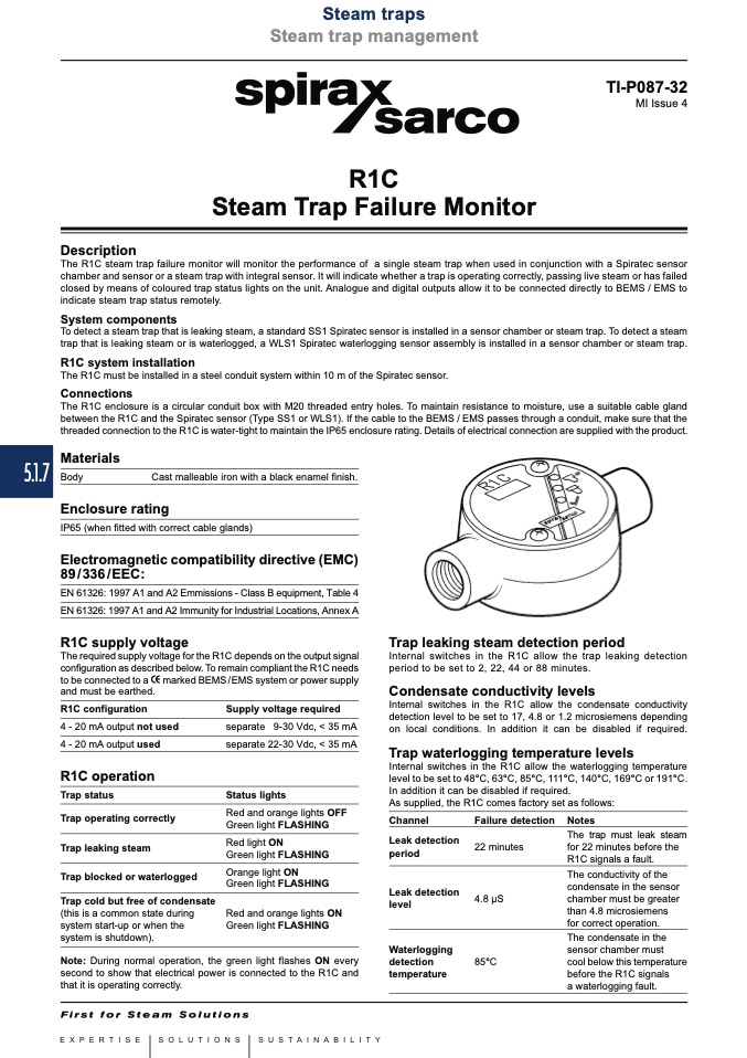
The R1C steam trap failure monitor will monitor the performance of a single steam trap when used in conjunction with a Spiratec sensor
chamber and sensor or a steam trap with integral sensor. It will indicate whether a trap is operating correctly, passing live steam or has failed
closed by means of coloured trap status lights on the unit. Analogue and digital outputs allow it to be connected directly to BEMS / EMS to
indicate steam trap status remotely.
System components
To detect a steam trap that is leaking steam, a standard SS1 Spiratec sensor is installed in a sensor chamber or steam trap. To detect a steam
trap that is leaking steam or is waterlogged, a WLS1 Spiratec waterlogging sensor assembly is installed in a sensor chamber or steam trap.
R1C system installation
The R1C must be installed in a steel conduit system within 10 m of the Spiratec sensor.
Connections
The R1C enclosure is a circular conduit box with M20 threaded entry holes. To maintain resistance to moisture, use a suitable cable gland
between the R1C and the Spiratec sensor (Type SS1 or WLS1). If the cable to the BEMS / EMS passes through a conduit, make sure that the
threaded connection to the R1C is water-tight to maintain the IP65 enclosure rating. Details of electrical connection are supplied with the product.
Materials
Body
Cast malleable iron with a black enamel finish.
Enclosure rating
IP65 (when fitted with correct cable glands)
Electromagnetic compatibility directive (EMC)
89/336/EEC:
EN 61326: 1997 A1 and A2 Emmissions - Class B equipment, Table 4
EN 61326: 1997 A1 and A2 Immunity for Industrial Locations, Annex A
R1C supply voltage
The required supply voltage for the R1C depends on the output signal
configuration as described below. To remain compliant the R1C needs
Trap leaking steam detection period
Internal switches in the R1C allow the trap leaking detection
period to be set to 2, 22, 44 or 88 minutes.
Condensate conductivity levels
Internal switches in the R1C allow the condensate conductivity
detection level to be set to 17, 4.8 or 1.2 microsiemens depending
on local conditions. In addition it can be disabled if required.
Trap waterlogging temperature levels
Internal switches in the R1C allow the waterlogging temperature
level to be set to 48°C, 63°C, 85°C, 111°C, 140°C, 169°C or 191°C.
In addition it can be disabled if required.
As supplied, the R1C comes factory set as follows:
to be connected to a
and must be earthed.
marked BEMS/EMS system or power supply
R1C configuration
4 - 20 mA output not used
4 - 20 mA output used
R1C operation
Trap status
Trap operating correctly
Trap leaking steam
Trap blocked or waterlogged
Trap cold but free of condensate
(this is a common state during
system start-up or when the
system is shutdown).
Supply voltage required
separate 9-30 Vdc, < 35 mA
separate 22-30 Vdc, < 35 mA
Status lights
Red and orange lights OFF
Green light FLASHING
Red light ON
Green light FLASHING
Orange light ON
Green light FLASHING
Red and orange lights ON
Green light FLASHING
green light flashes ON every
Channel
Leak detection
period
Leak detection
level
Failure detection
22 minutes
4.8 μS
Notes
The trap must leak steam
for 22 minutes before the
R1C signals a fault.
The conductivity of the
condensate in the sensor
chamber must be greater
than 4.8 microsiemens
for correct operation.
The condensate in the
sensor chamber must
cool below this temperature
before the R1C signals
a waterlogging fault.
Note: During normal operation, the
second to show that electrical power is connected to the R1C and
that it is operating correctly.
Waterlogging
detection
85°C
temperature

