Control valves
Level indicators
Page 7 of 8
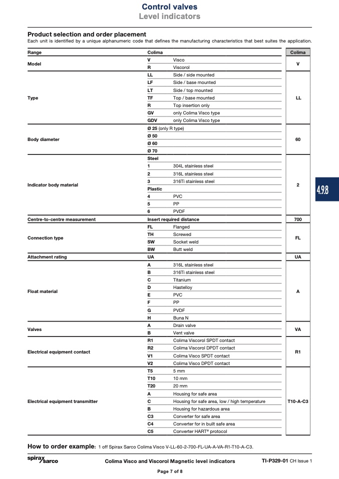
Product selection and order placement
Each unit is identified by a unique alphanumeric code that defines the manufacturing characteristics that best suites the application.
Range
Colima
Model
V
R
LL
LF
LT
Type
TF
Colima
Visco
V
Viscorol
Side / side mounted
Side / base mounted
Side / top mounted
Top / base mounted
LL
R
GV
GDV
Ø 25
Ø 50
Ø 60
Ø 70
Steel
1
2
3
Plastic
4
5
6
Top insertion only
only Colima Visco type
only Colima Visco type
(only R type)
Body diameter
Indicator body material
Centre-to-centre measurement
Connection type
Attachment rating
Float material
Valves
Electrical equipment contact
Electrical equipment transmitter
60
304L stainless steel
316L stainless steel
316Ti stainless steel
2
PVC
PP
PVDF
Insert required distance
700
FL
Flanged
TH
Screwed
FL
SW
Socket weld
BW
Butt weld
UA
UA
A
316L stainless steel
B
316Ti stainless steel
C
Titanium
D
Hastelloy
A
E
PVC
F
PP
G
PVDF
H
Buna N
A
Drain valve
VA
B
Vent valve
R1
Colima Viscorol SPDT contact
R2
Colima Viscorol DPDT contact
R1
V1
Colima Visco SPDT contact
V2
Colima Visco DPDT contact
T5
5 mm
T10
10 mm
T20
20 mm
A
Housing for safe area
C
Housing for safe area, low / high temperature
B
Housing for hazardous area
C3
Converter for safe area
C4
Converter for in built safe area
C5
Converter HART
®
protocol
T10-A-C3
How to order example: 1 off Spirax Sarco Colima Visco V-LL-60-2-700-FL-UA-A-VA-R1-T10-A-C3.
Colima Visco and Viscorol Magnetic level indicators
TI-P329-01 CH Issue 1
Page 7 of 8
4.9.8

