Control valves
Desuperheaters
Detailed example (continued)
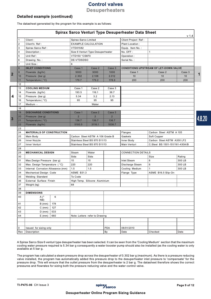
The datasheet generated by the program for this example is as follows:
Spirax Sarco Venturi Type Desuperheater Data Sheet
v 1.4
1
Client :
Spirax-Sarco Limited
Client Project Ref :
2
Client's Ref :
EXAMPLE CALCULATION
Plant Location :
3
Spirax Sarco Ref :
VTD01582
Equip. Item No. :
4
Description :
Size 6 Venturi Type Desuperheater
No. OFF :
1
5
Unit Ref :
VTD150 °CS6F0
Operation :
6
Drawing No. :
DE-VTDSDSO
Serial No. :
7
Unit Size :
6
8
INLET CONDITIONS
Case 1
Case 2
Case 3
CONDITIONS UPSTREAM OF LET-DOWN VALVE
2
9
Flowrate (kg/hr)
5000
3000
1000
Case 1
Case 2
Case 3
1
10
Pressure (bar g)
2.302
2.108
2.012
10
10
10
11
Temperature ( °C)
179.7
179.2
178.9
200
200
200
12
13
COOLING MEDIUM
Case 1
Case 2
Case 3
4
14
Flowrate (kg/hr)
193.5
116.1
38.7
15
Pressure (bar g)
5.34
3.2
2.13
16
Temperature ( °C)
95
95
95
17
Medium -
Water
18
19
DISCHARGE CONDITIONS
Case 1
Case 2
Case 3
3
20
Pressure (bar g)
2
2
2
21
Temperature ( °C)
136.7
136.7
136.7
22
Flowrate (kg/hr)
5193.5
3116.1
1038.7
23
24
MATERIALS OF CONSTRUCTION
Flanges
Carbon Steel ASTM A 105
25
Main Body
Carbon Steel ASTM A 106 Grade B
Gaskets
Soft Copper
26
Inner Nozzle
Stainless Steel BS 970 S11/13
Inner Body
Carbon Steel ASTM A350 LF2
27
Inner Venturi
Stainless Steel BS 970 S11/13
Main Venturi
C.Steel BS 1501-151/161-430A/B
28
29
MECHANICAL DESIGN
Steam
Water
CONNECTION DETAILS
30
Side
Side
Size
Rating
31
Max.Design Pressure (bar g)
15
15
Inlet Steam
6
300 LB
32
Max. Design Temperature ( °C)
220
220
Discharge Steam
6
300 LB
33
Internal Corrosion Allowance (mm)
1.5
1.5
Cooling Medium
1
300 LB
34
Mechanical Design Code
ASME B31.3
Flange Type
ASME B16.5 Slip-On
35
Welding Standard
To Code
36
External Surface Finish
High Temp. Silicone Aluminium
37
Weight (kg)
68
38
39
DIMENSIONS
40
A ("
NB)
6
41
B (mm)
178
42
C (mm)
127
43
D (mm)
533
44
E (mm)
660
Note: Letters refer to Drawing
0
Issued for sizing only
PDA
08/01/2010
Rev
Description
By
A Spirax Sarco Size 6 venturi type desuperheater has been selected. It can be seen from the 'Cooling Medium' section that the maximum
cooling water pressure required is 5.34 bar g consequently a water booster pump should also be installed (as the cooling water is only
available at 5 bar g.
The program has calculated a steam pressure drop across the desuperheater of 0.302 bar g (maximum). As there is a pressure reducing
valve installed, the program has automatically added this pressure drop to the desuperheater inlet pressure to 'compensate' for the
pressure drop. This will ensure that the outlet pressure from the desuperheater is 2 bar g. The datasheet therefore shows the correct
pressures and flowrates for sizing both the pressure reducing valve and the water control valve.
Date
Checked
Date
TI-P475-06 CH Issue 3
Page 9 of 12
Desuperheater Online Program Sizing Guidance
4.8.20

