Control valves
Desuperheaters
4.8.15
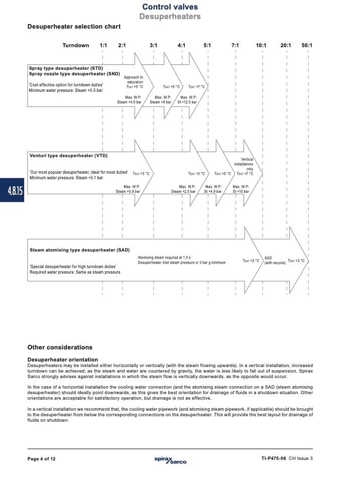
Desuperheater selection chart
Turndown
1:1
2:1
Spray type desuperheater (STD)
3:1
4:1
5:1
7:1
10:1
20:1
50:1
Spray nozzle type desuperheater (SND)
'Cost effective option for turndown duties'
Minimum water pressure: Steam +0.5 bar
Venturi type desuperheater (VTD)
Approach to
saturation
Tsat +5 °C
Tsat +5 °C
Tsat +7 °C
Max. W.P:
Max. W.P:
Steam +4.5 bar
Max. W.P:
Steam +8 bar
St +12.5 bar
Tsat +3 °C
'Our most popular desuperheater, ideal for most duties'
Minimum water pressure: Steam +0.1 bar
Tsat +3 °C
Max. W.P:
Steam +0.9 bar
Steam atomising type desuperheater (SAD)
'Special desuperheater for high turndown duties'
Required water pressure: Same as steam pressure
Other considerations
Desuperheater orientation
Vertical
installations
only
Tsat +5 °C Tsat +7 °C
Max. W.P:
Steam +2.5 bar
Max. W.P:
Max. W.P:
St +4.9 bar
St +10 bar
Atomising steam required at 1.5 x
Desuperheater inlet steam pressure or 3 bar g minimum
Tsat +3 °C
SAD
(with recycle)
Tsat +3 °C
Desuperheaters may be installed either horizontally or vertically (with the steam flowing upwards). In a vertical installation, increased
turndown can be achieved; as the steam and water are countered by gravity, the water is less likely to fall out of suspension. Spirax
Sarco strongly advises against installations in which the steam flow is vertically downwards, as the opposite would occur.
In the case of a horizontal installation the cooling water connection (and the atomising steam connection on a SAD (steam atomising
desuperheater) should ideally point downwards, as this gives the best orientation for drainage of fluids in a shutdown situation. Other
orientations are acceptable for satisfactory operation, but drainage is not as effective.
In a vertical installation we recommend that, the cooling water pipework (and atomising steam pipework, if applicable) should be brought
to the desuperheater from below the corresponding connections on the desuperheater. This will provide the best layout for drainage of
fluids on shutdown.
Page 4 of 12
TI-P475-06 CH Issue 3

