Control valves
Safety valves
Page 1 of 5
TI-S13-25
CH Issue 11
Cert. No. LRQ 0963008
SV73
Cast Iron
Safety Valve
Description
The SV73 cast iron series valves are built in conformance to Section I and VIII of the ASME Boiler and Pressure Vessel Code. They are
primarily intended for use on power boilers and unfired pressure vessels where ASME Section I and VIII stamped valves are required.
Applications
Protection of steam systems downstream of pressure regulating stations, on inlet to such equipment as air coils, heat exchangers and
process vessels. Also for use on flash recovery vessels on condensate return systems to protect vessels. Air systems to protect accumulation
vessels and air equipment from overpressurisation. Steam boilers and generators.
Available types
The SV73 is available with cast iron body and stainless steel trim in orifice sizes from 'J' to 'R'. It has an open bonnet and easing lever and is
available with screwed or flanged connections.
Certification
A manufacturers' Typical Test Report is provided as standard for each valve which will include valve set and hydraulic test pressure. Also
available on request is material certification in accordance with EN 10204 3.1.
Standards and approvals
Approved by National Board of Boiler and Pressure Vessel Inspectors to ASME Boiler and Pressure Vessel Code Sections I and VIII.
Seat tightness is in accordance with ANSI/API STD 527-1992.
If National Board 'V' or 'UV' stamp is required, then this must be specified at the time of ordering.
Important note: SV73 safety valves are not marked and therefore not to be used within the EEA.
Sizes and end connections
11⁄2" x 21⁄2" to 3" x 4"
11⁄2" x 21⁄2" to 3" x 4"
3" x 4" to 6" x 8"
Inlet /outlet screwed female NPT.
Inlet flanged ANSI class 250 RF,
Inlet flanged ANSI class 250 RF,
Outlet screwed female NPT.
Outlet flanged ANSI class 125 FF.
���
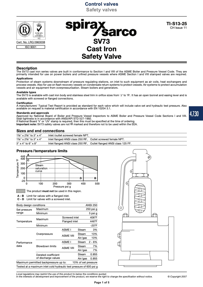
Pressure/temperature limits
���
A
���
���
���
���
�
���
�
���
���
���
Pressure psi g
���
The product must not be used in this region.
A - B Limit for valves with a flanged inlet.
C - D Limit for valves with a screwed inlet.
Body design conditions
ANSI 250
250 psi g
5 psi g
406°F
446°F
-20°F
Steam
3%
Steam
10%
Air / gas
10%
Steam 2 - 6%
Steam
7%
Tested at a maximum inlet cold hydraulic test pressure of 600 psi g
Local regulations may restrict the use of this product to below the conditions quoted.
In the interests of development and improvement of the product, we reserve the right to change the specification without notice.
Set pressure
range
Temperature
Performance
data
Maximum
Minimum
Maximum
Minimum
Overpressure
Blowdown limits
Screwed inlet
Flanged inlet
ASME I
ASME VIII
ASME I
ASME VIII
ISO 9001
C
Steam
saturation
curve
D
B
7%
0.955
0.955
Maximum permitted backpressure up to:
10% of set pressure
Derated coefficient
of discharge values
Air / gas
Steam
Air / gas
Page 1 of 5
© Copyright 2007
4.7.30
T
e
m
p
e
r
a
t
u
r
e
°
F

