Control valves
Safety valves
Page 5 of 5
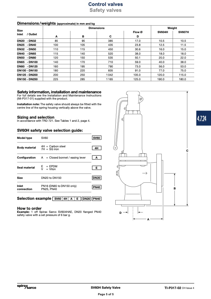
Dimensions/weights (approximate) in mm and kg
Size
Inlet / Outlet
DN20 - DN32
DN25 - DN40
DN32 - DN50
DN40 - DN65
DN50 - DN80
DN65 - DN100
DN80 - DN125
DN100 - DN150
DN125 - DN200
DN150 - DN250
Safety information, installation and maintenance
For full details see the Installation and Maintenance Instructions
(IM-P317-01) supplied with the product.
Installation note: The safety valve should always be fitted with the
centre line of the spring housing vertically above the valve.
Sizing and selection
In accordance with TRD 721. See Tables 1 and 2, page 4.
SV60H safety valve selection guide:
Weight
SV604H
SV607H
10.5
11.5
15.0
18.0
22.0
38.0
53.0
75.0
115.0
180.0
Dimensions
A
B
C
D
85
100
110
115
120
140
160
180
200
225
95
105
115
140
150
170
195
220
250
285
385
435
450
520
535
710
790
835
1 042
1 165
Flow Ø
17.0
23.8
30.6
38.0
50.1
59.0
73.0
91.0
105.0
125.0
10.5
12.5
16.0
18.0
20.0
40.0
56.0
77.0
120.0
190.0
Model type
Body material
Configuration
Seal material
Size
Inlet
connection
SV60
4H = Carbon steel
7H = SG iron
A = Closed bonnet / easing lever
E =EPDM
V = Viton
DN20 to DN150
PN16 (DN65 to DN150 only)
PN25, PN40
C
SV60
4H
A
E
DN20
PN40
B
Selection example
How to order
Example: 1 off Spirax Sarco SV604HAE, DN20 flanged PN40
safety valve with a set pressure of 6 bar g.
D
SV60 4H A
E
DN20
PN40
A
SV60H Safety Valve
TI-P317-02 CH Issue 4
Page 5 of 5
4.7.24

