Control valves
Pressure reducing/surplussing valves
Page 1 of 3
TI-P186-05
CH Issue 7
Cert. No. LRQ 0963008
Description
SRV2S
Stainless Steel
Pressure Reducing Valve
ISO 9001
18
2
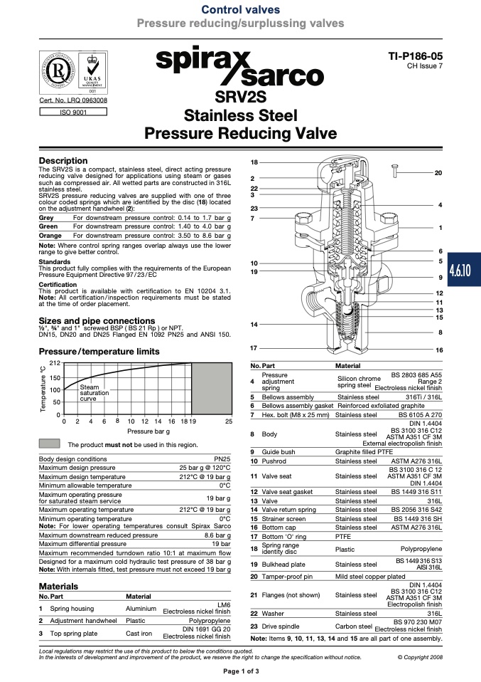
on the adjustment handwheel (2):
23
Grey
For downstream pressure control: 0.14 to 1.7 bar g
7
Green
For downstream pressure control: 1.40 to 4.0 bar g
Orange
For downstream pressure control: 3.50 to 8.6 bar g
Note: Where control spring ranges overlap always use the lower
range to give better control.
Pressure Equipment Directive 97/23/EC
Certification
This product is available with certification to EN 10204 3.1.
Note: All certification/inspection requirements must be stated
at the time of order placement.
Sizes and pipe connections
1⁄2", 3⁄4" and 1" screwed BSP ( BS 21 Rp ) or NPT.
DN15, DN20 and DN25 Flanged EN 1092 PN25 and ANSI 150.
Pressure/temperature limits
���
���
���
��
�
� � � � � �� �� �� �� ����
��
Pressure bar g
The product must not be used in this region.
The SRV2S is a compact, stainless steel, direct acting pressure
reducing valve designed for applications using steam or gases
such as compressed air. All wetted parts are constructed in 316L
stainless steel.
22
SRV2S pressure reducing valves are supplied with one of three
3
colour coded springs which are identified by the disc (18) located
20
4
1
6
5
9
12
11
13
15
8
16
Standards
10
This product fully complies with the requirements of the European
19
14
17
No. Part
Pressure
4 adjustment
spring
5 Bellows assembly
6 Bellows assembly gasket
7 Hex. bolt (M8 x 25 mm)
8 Body
9 Guide bush
10 Pushrod
11 Valve seat
12 Valve seat gasket
13 Valve
14 Valve return spring
15 Strainer screen
16 Bottom cap
17 Bottom 'O' ring
18
Spring range
identity disc
19 Bulkhead plate
20 Tamper-proof pin
21 Flanges (not shown)
22 Washer
Material
Silicon chrome
spring steel
Steam
saturation
curve
BS 2803 685 A55
Range 2
Electroless nickel finish
Stainless steel
316Ti / 316L
Reinforced exfoliated graphite
Stainless steel
BS 6105 A 270
Body design conditions
Maximum design pressure
Maximum design temperature
Minimum allowable temperature
Maximum operating pressure
for saturated steam service
Maximum operating temperature
Stainless steel
Graphite filled PTFE
PN25
25 bar g @ 120°C
212°C @ 19 bar g
0°C
19 bar g
212°C @ 19 bar g
19 bar
Aluminium
LM6
Electroless nickel finish
Plastic
Polypropylene
Cast iron
DIN 1691 GG 20
Electroless nickel finish
Stainless steel
Stainless steel
Stainless steel
Stainless steel
Stainless steel
Stainless steel
Stainless steel
PTFE
Plastic
ASTM A276 316L
BS 3100 316 C 12
ASTM A351 CF 3M
DIN 1.4404
BS 1449 316 S11
316L
BS 2056 316 S42
BS 1449 316 SH
ASTM A276 316L
Polypropylene
BS 1449 316 S13
AISI 316L
DIN 1.4404
BS 3100 316 C12
ASTM A351 CF 3M
External electropolish finish
Minimum operating temperature
Note: For lower operating temperatures consult Spirax Sarco
Maximum downstream reduced pressure
Maximum differential pressure
Maximum recommended turndown ratio 10:1 at maximum flow
Designed for a maximum cold hydraulic test pressure of 38 bar g
Note: With internals fitted, test pressure must not exceed 19 bar g
Stainless steel
Mild steel copper plated
0°C
8.6 bar g
Materials
No. Part
1 Spring housing
2 Adjustment handwheel
3 Top spring plate
Material
Stainless steel
Stainless steel
DIN 1.4404
BS 3100 316 C12
ASTM A351 CF 3M
Electropolish finish
316L
23 Drive spindle
BS 970 230 M07
Electroless nickel finish
Carbon steel
Note: Items 9, 10, 11, 13, 14 and 15 are all part of one assembly.
Local regulations may restrict the use of this product to below the conditions quoted.
In the interests of development and improvement of the product, we reserve the right to change the specification without notice.
© Copyright 2008
Page 1 of 3
4.6.10
T
e
m
p
e
r
a
t
u
r
e
°
C

