Control valves
Pressure reducing/surplussing valves
Page 2 of 3
�
�
�
�
�
�
�
Up stream pressure bar g
(x 100 = kPa)
4.6.3
Capacities for safety valve sizing
Full lift capacities for safety valve sizing purposes :
Size
Kvs
For conversions:
Cv (UK) = Kv x 0.963
Cv (US) = Kv x 1.156
Steam and compressed air capacities
DN15
1.5
��
DN20
DN25
2.5
3.0
�� ��
��
��
���
�
�
�
�
�
�
�
�
�
Steam
capacity
kg/h
Compressed air
capacity dm
3
/s*
free air
��
��
��
��
���
���
���
���
���
���
���
���
���
��� 1⁄2"-DN15
���
��� 3⁄4" - DN20
���
��� 1" - DN25
�
�
�
�
�
�
���
���
���
��
��
��
��
��
��
��
��
��
���
1⁄2"-DN15
��
��
��
��
��
��
��
��
��
���
���
���
��
��
��
��
���
���
���
���
���
3⁄4" - DN20
1" - DN25
* dm
3
/s = I/s, 1 I/s2 c.f.m.
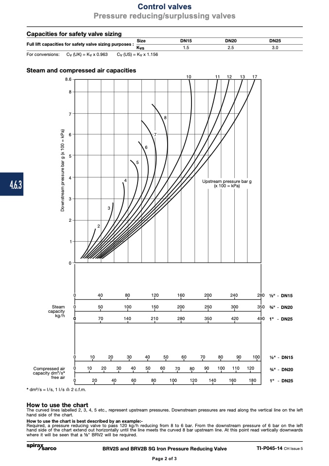
How to use the chart
The curved lines labelled 2, 3, 4, 5 etc., represent upstream pressures. Downstream pressures are read along the vertical line on the left
hand side of the chart.
How to use the chart is best described by an example:-
Required, a pressure reducing valve to pass 120 kg/h reducing from 8 to 6 bar. From the downstream pressure of 6 bar on the left
hand side of the chart extend out horizontally until the line meets the curved 8 bar upstream line. At this point read vertically downwards
where it will be seen that a 1⁄2" BRV2 will be required.
BRV2S and BRV2B SG Iron Pressure Reducing Valve
TI-P045-14 CH Issue 5
Page 2 of 3
D
o
w
n
s
t
r
e
a
m
p
r
e
s
s
u
r
e
b
a
r
g
(
x
1
0
0
=
k
P
a
)

