Control valves
Self-acting controls
Page 5 of 12
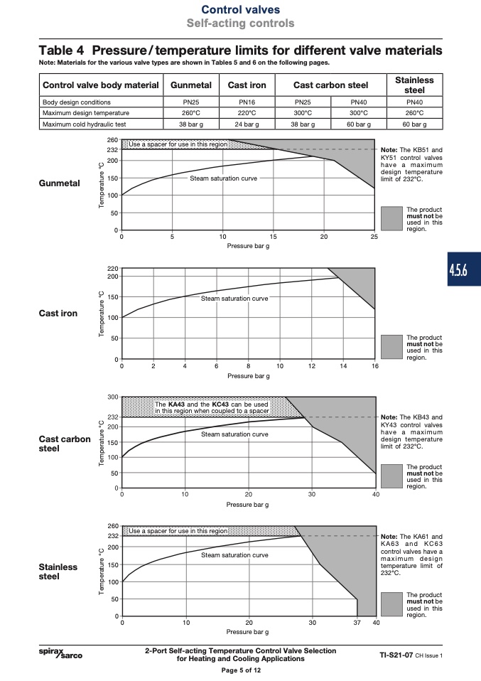
Table 4 Pressure/temperature limits for different valve materials
Note: Materials for the various valve types are shown in Tables 5 and 6 on the following pages.
Control valve body material
Gunmetal
Cast iron
Cast carbon steel
Stainless
steel
Body design conditions
PN25
PN16 PN25 PN40 PN40
Maximum design temperature
260°C
220°C 300°C 300°C 260°C
Maximum cold hydraulic test
38 bar g
24 bar g 38 bar g 60 bar g 60 bar g
Use a spacer for use in this region
Steam satu ration curve
Gunmetal
���
���
���
���
���
��
�
���
���
���
���
��
�
Note: The KB51 and
KY51 control valves
have a maximum
design temperature
limit of 232°C.
The product
must not be
used in this
region.
�
�
��
��
��
��
Pressure bar g
Steam saturation curve
Cast iron
�
�
�
�
�
��
��
��
��
The product
must not be
used in this
region.
Note: The KB43 and
KY43 control valves
have a maximum
design temperature
limit of 232°C.
The product
must not be
used in this
region.
Note: The KA61 and
KA63 and KC63
control valves have a
maximum design
temperature limit of
232°C.
The product
must not be
used in this
region.
Pressure bar g
The KA43 and the KC43 can be used
in this region when coupled to a spacer
Steam saturation curve
Cast carbon
���
steel
��
���
���
���
���
���
��
�
Pressure bar g
Use a spacer for use in this region
Steam saturation curve
Stainless
steel
�
��
��
��
�
�
��
Pressure bar g
2-Port Self-acting Temperature Control Valve Selection
for Heating and Cooling Applications
TI-S21-07 CH Issue 1
Page 5 of 12
4.5.6
T
e
m
p
e
r
a
t
u
r
e
°
C
T
e
m
p
e
r
a
t
u
r
e
°
C
T
e
m
p
e
r
a
t
u
r
e
°
C
T
e
m
p
e
r
a
t
u
r
e
°
C

