Control valves
Self-acting controls
Page 3 of 12
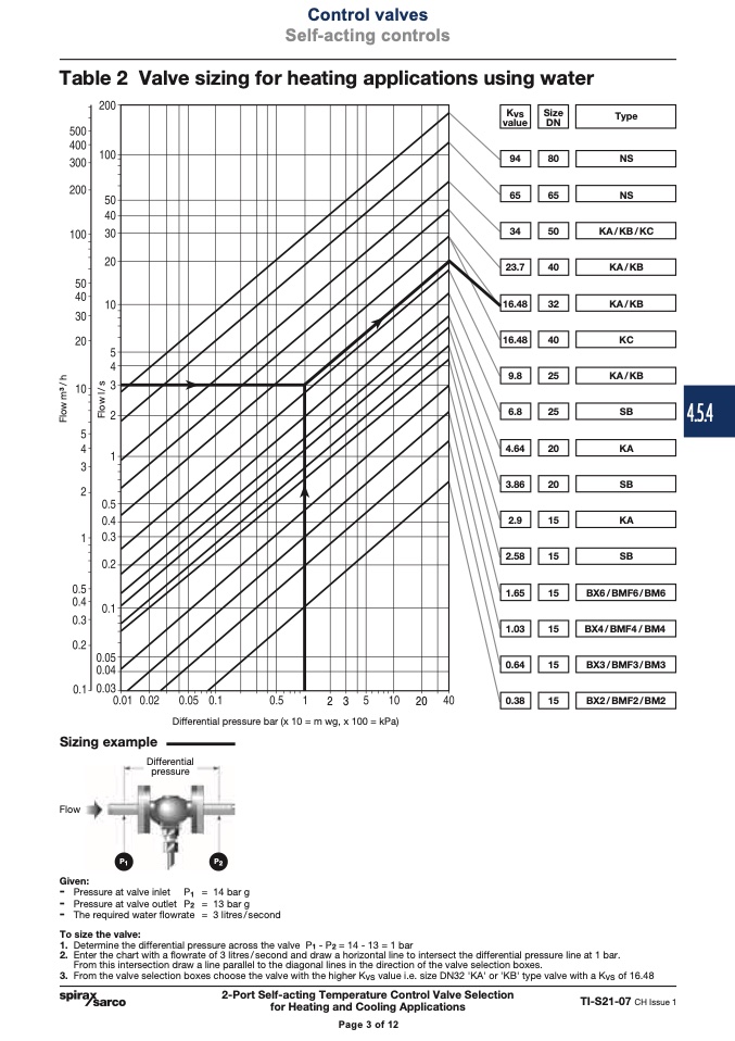
Table 2 Valve sizing for heating applications using water
Kvs
value
Size
DN
Type
9
4
80
NS
6
5
65
NS
34
50
23.7
40
16.48
32
KA/KB/KC
KA/KB
KA/KB
16.48
40
KC
KA/KB
6.8
25
SB
4.64
20
KA
3.86
20
SB
2.9
15
KA
2.58
15
SB
9.8
25
1.65
15
1.03
15
0.64
15
��
��
0.38
15
Differential pressure bar (x 10 = m wg, x 100 = kPa)
BX6/BMF6/ BM6
BX4/BMF4/ BM4
BX3/BMF3/ BM3
BX2/BMF2/BM2
Sizing example
Flow
Differential
pressure
P1
P2
Given:
- Pressure at valve inlet P
1
= 14 bar g
- Pressure at valve outlet P
2
= 13 bar g
- The required water flowrate = 3 litres/second
To size the valve:
1. Determine the differential pressure across the valve P
1
- P2 = 14 - 13 = 1 bar
2. Enter the chart with a flowrate of 3 litres / second and draw a horizontal line to intersect the differential pressure line at 1 bar.
From this intersection draw a line parallel to the diagonal lines in the direction of the valve selection boxes.
3. From the valve selection boxes choose the valve with the higher Kvs value i.e. size DN32 'KA' or 'KB' type valve with a Kvs of 16.48
2-Port Self-acting Temperature Control Valve Selection
for Heating and Cooling Applications
TI-S21-07 CH Issue 1
Page 3 of 12
4.5.4
F
l
o
w
m
3
/
h
F
l
o
w
l
/
s

