Control valves
Self-acting controls
Page 1 of 12
TI-S21-07
CH Issue 1
Cert. No. LRQ 0963008
2-Port Self-acting Temperature
ISO 9001
Control Valve Selection
for Heating and Cooling Applications
How to select a system
Valve selection:
1. Is the application for heating or cooling?
A heating application will require a valve that is normally open and will close with rising temperature.
A cooling application will require a valve that is normally closed and will open with rising temperature.
2. Is the valve to be used on steam or water applications?
For steam applications use the sizing chart in Table 1 on page 2.
For water heating applications use the chart in Table 2 on page 3.
For water cooling applications use the chart in Table 3 on page 4.
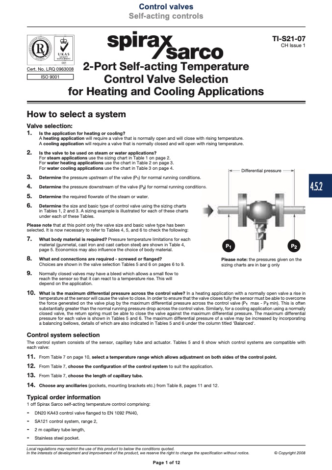
3. Determine the pressure upstream of the valve (P
1
) for normal running conditions.
Differential pressure
4. Determine the pressure downstream of the valve (P
2
) for normal running condition
5. Determine the required flowrate of the steam or water.
6. Determine the size and basic type of control valve using the sizing charts
in Tables 1, 2 and 3. A sizing example is illustrated for each of these charts
under each of these Tables.
Please note that at this point only the valve size and basic valve type has been
selected. It is now necessary to refer to Tables 4, 5, and 6 to check the following:
7. What body material is required? Pressure temperature limitations for each
material (gunmetal, cast iron and cast carbon steel) are shown in Table 4,
page 5. Economics may also influence the choice of body material.
8. What end connections are required - screwed or flanged?
Choices are shown in the valve selection Tables 5 and 6 on pages 6 to 9.
9. Normally closed valves may have a bleed which allows a small flow to
reach the sensor so that it can react to a temperature rise. This will
depend on the application.
ns
s .
.
10. What is the maximum differential pressure across the control valve? In a heating application with a normally open valve a rise in
temperature at the sensor will cause the valve to close. In order to ensure that the valve closes fully the sensor must be able to overcome
the force generated on the valve plug by the maximum differential pressure across the control valve (P1 max - P2 min). This is often
substantially greater than the normal running pressure drop across the control valve. Similarly, for a cooling application using a normally
closed valve, the return spring must be able to close the valve against the maximum differential pressure. The maximum differential
pressure for each valve is shown in Tables 5 and 6. The maximum differential pressure of a valve may be increased by incorporating
a balancing bellows, details of which are also indicated in Tables 5 and 6 under the column titled 'Balanced'.
Control system selection
The control system consists of the sensor, capillary tube and actuator. Tables 5 and 6 show which control systems are compatible with
each valve:
11. From Table 7 on page 10, select a temperature range which allows adjustment on both sides of the control point.
12. From Table 7, choose the configuration of the control system to suit the application.
13. From Table 7, choose the length of capillary tube.
14. Choose any ancillaries (pockets, mounting brackets etc.) from Table 8, pages 11 and 12.
Typical order information
1 off Spirax Sarco self-acting temperature control comprising:
- DN20 KA43 control valve flanged to EN 1092 PN40,
- SA121 control system, range 2,
- 2 m capillary tube length,
- Stainless steel pocket.
Local regulations may restrict the use of this product to below the conditions quoted.
In the interests of development and improvement of the product, we reserve the right to change the specification without notice.
© Copyright 2008
P1
P2
Please note: the pressures given on the
sizing charts are in bar g only
Page 1 of 12
4.5.2

