Control valves
Electric actuators
Safety information, installation and maintenance
For full details see the Installation and Maintenance Instructions (IM-P358-26) supplied with the product.
Installation and wiring note:
The valve should be installed in the horizontal line. The position of the actuator will depend on the type of valve to which it is fitted and
the temperature of the media. However, it is not recommended that the actuators be fitted directly below the valve or in a wet environment.
Disposal
This product is recyclable. No ecological hazard is anticipated with the disposal of this product, providing due care is taken.
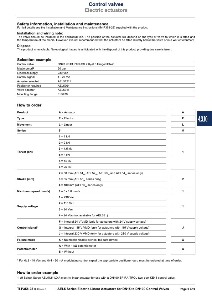
Selection example
Control valve
Maximum DP
Electrical supply
Control signal
Actuator selected
Positioner required
Valve adaptor
Mounting flange
How to order
Product
Type
Movement
Series
Thrust (kN)
Stroke (mm)
Maximum speed (mm/s)
Supply voltage
Control signal*
Failure mode
Potentiometer
DN20 KE43 PTSUSS.2 Kv 6.3 flanged PN40
20 bar
230 Vac
4 - 20 mA
AEL51211
AEL5961
AEL6911
EL5970
A = Actuator
E = Electric
L = Linear
5
1 = 1 kN
2 = 2 kN
3 = 4.5 kN
4 = 8 kN
5 = 14 kN
6 = 25 kN
2 = 50 mm (AEL51_, AEL52_, AEL53_ and AEL54_ series only)
3 = 65 mm (AEL55_ series only)
4 = 100 mm (AEL56_ series only)
1 = 0 - 1.0 mm/s
1 = 230 Vac
2 = 115 Vac
3 = 24 Vac
4 = 24 Vdc (not available for AEL56_)
F = Integral 24 V VMD (only for actuators with 24 V supply voltage)
G = Integral 115 V VMD (only for actuators with 115 V supply voltage)
J = Integral 230 V VMD (only for actuators with 230 V supply voltage)
X = No mechanical / electrical fail safe device
A = With 1 kΩ potentiometer
S = Without
A
E
L
5
1
2
1
1
J
X
A
* For 0/2 - 10 Vdc and 0/4 - 20 mA modulating control signal the appropriate positioner card must be ordered at time of order.
How to order example
1 off Spirax Sarco AEL51211JXA electric linear actuator for use with a DN100 SPIRA-TROL two-port KE43 control valve.
TI-P358-25 CH Issue 3
AEL5 Series Electric Linear Actuators for DN15 to DN100 Control Valves
Page 9 of 9
4.3.10

