Control valves
Control valves
A
Steam
saturation
curve
G
E
F
4.1.31
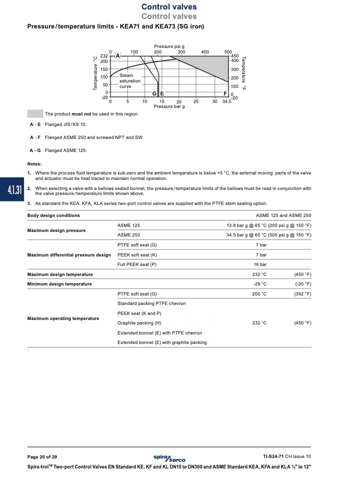
Pressure / temperature limits - KEA71 and KEA73 (SG iron)
��
������
������
������
����
��
������
��
��
The product must not be used in this region.
Flanged JIS/KS 10.
Pressure psi g
������
������
����
����
����
Pressure bar g
������
������
������
������
������
������
������
������
������
��
A - E
A - F
A - G
Flanged ASME 250 and screwed NPT and SW.
Flanged ASME 125.
Body design conditions
Maximum design pressure
Maximum differential pressure design
Maximum design temperature
Minimum design temperature
Maximum operating temperature
.
ASME 125 and ASME 250
����
���� ��������
������
Notes:
1. Where the process fluid temperature is sub-zero and the ambient temperature is below +5 °C, the external moving parts of the valve
and actuator must be heat traced to maintain normal operation.
2. When selecting a valve with a bellows sealed bonnet, the pressure / temperature limits of the bellows must be read in conjunction with
the valve pressure / temperature limits shown above.
3. As standard the KEA, KFA, KLA series two-port control valves are supplied with the PTFE stem sealing option.
ASME 125
ASME 250
PTFE soft seat (G)
PEEK soft seat (K)
Full PEEK seat (P)
PTFE soft seat (G)
Standard packing PTFE chevron
PEEK seat (K and P)
Graphite packing (H)
Extended bonnet (E) with PTFE chevron
Extended bonnet (E) with graphite packing
13.8 bar g @ 65 °C
34.5 bar g @ 65 °C
7 bar
7 bar
19 bar
232 °C
-29 °C
200 °C
232 °C
(200 psi g @ 150 °F)
(500 psi g @ 150 °F)
(450 °F)
(-20 °F)
(392 °F)
(450 °F)
TI-S24-71 CH Issue 10
Spira-trol
TM
Two-port Control Valves EN Standard KE, KF and KL DN15 to DN300 and ASME Standard KEA, KFA and KLA 1⁄2" to 12"
Page 20 of 29
T
e
m
p
e
r
a
t
u
r
e
°
F
T
e
m
p
e
r
a
t
u
r
e
°
C

