Control valves
Control valves
F
Steam
saturation
curve
F
E
D
C
B
4.1.21
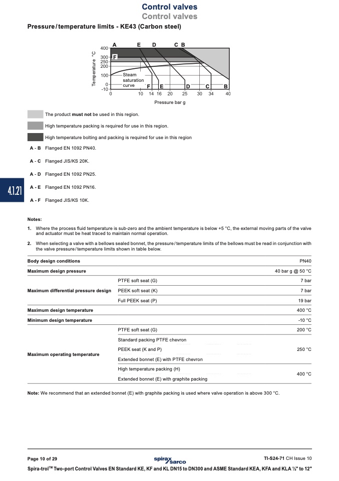
Pressure / temperature limits - KE43 (Carbon steel)
A
E
D
CB
Pressure bar g
The product must not be used in this region.
High temperature packing is required for use in this region.
High temperature bolting and packing is required for use in this region
A-B Flanged EN 1092 PN40.
A-C Flanged JIS/KS 20K.
A-D Flanged EN 1092 PN25.
A-E Flanged EN 1092 PN16.
A-F Flanged JIS/KS 10K.
Notes:
1. Where the process fluid temperature is sub-zero and the ambient temperature is below +5 °C, the external moving parts of the valve
and actuator must be heat traced to maintain normal operation.
2. When selecting a valve with a bellows sealed bonnet, the pressure / temperature limits of the bellows must be read in conjunction with
the valve pressure / temperature limits shown in table below.
Body design conditions
Maximum design pressure
Maximum differential pressure design
Maximum design temperature
Minimum design temperature
Maximum operating temperature
PTFE soft seat (G)
PEEK soft seat (K)
Full PEEK seat (P)
PTFE soft seat (G)
Standard packing PTFE chevron
PEEK seat (K and P)
Extended bonnet (E) with PTFE chevron
High temperature packing (H)
Extended bonnet (E) with graphite packing
PN40
40 bar g @ 50 °C
7 bar
7 bar
19 bar
400 °C
-10 °C
200 °C
250 °C
400 °C
Note: We recommend that an extended bonnet (E) with graphite packing is used where valve operation is above 300 °C.
Page 10 of 29
TI-S24-71 CH Issue 10
Spira-trol
TM
Two-port Control Valves EN Standard KE, KF and KL DN15 to DN300 and ASME Standard KEA, KFA and KLA 1⁄2" to 12"
T
e
m
p
e
r
a
t
u
r
e
°
C

