Flowmetering
Vortex flowmeters
3.7.3
Some typical piping configurations / considerations
Upstream Downstream
One 90° elbow before the flowmeter 10 D 5D
Two 90° elbows belore the flowmeter
10 D 5D
Two 90° elbows out of plane before the flowmeter
30 D 5D
Reduction before the flowmeter
10 D 5D
Regulator or valve partially closed
30 D 5D
Materials - Wetted parts
Wing and shedder bar
Flow tube
Electronics enclosure
Aluminium 383
All other parts
Stainless steel and Carbon steel Models 316L or the cast equivalent, CF3M
Stainless steel model (all sizes) 316L or the cast equivalent, CF3M
Carbon steel model (flanged), DN150 (6") and larger ASTM A105, A06 Grade C, and A108 Grade 1018
Approved for NEMA 4x for water tight and dust tight requirements
Physical specifications
Stainless steel 316L and Aluminium 383
Flowmeter classification
Standard
Explosion proof version
Designed to meet NEMA 4X watertight and dust tight specifications
Local indicator and totalizer
FMus certification
FMc is pending
ATEX
Class I, Division II, Groups B,C,D and Dust-ignition Proof for Class II, Division III,
Groups F, and G Hazardous locations.
II3GExnAIICT6Ta
= 0to+60°CIP66
II3DExtcIIICT70°CTa = 0to+60°CIP66
The indicator displays flowrate and total in user-selectable, engineering units. The OLED display has selectable character sizes.
The totalizer enables a pulse output providing a 5 - 999 msec pulse each time the totalizer increments.
Remote mount electonics
Signal cable is provided to mount the electronics enclosure up to 30 m (100 ft) from the flowmeter flow tube, and must be installed
within proper electrical conduit.
Straight run piping requirements
Typical 10 diameters upstream, 5 diameters downstream. In certain applications where multiple bends or butterfly valves are present,
more straight run may be required.
Other installation considerations
Installation
A flowmeter can be installed vertically, horizontally, or at any
angle. For liquid service, the flow line must remain full during
flowmeter operation.
Site selection
The flow measurement location should be selected to minimize
turbulence and swirl. The extent of these flow disturbances
depends upon the piping configuration. Valves, elbows,
pumps and other piping components may add disturbances
to the flow.
Serviceability
The sensor element and temperature sensor can be
removed, and replaced, without removing the flowmeter
body from the process line, and without process shut
down for process pressures below 52 bar g (750 psi g).
The flowmeter K-factor is not affected by sensor or electronics
servicing.
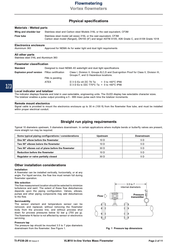
Pressure tap
The pressure tap should be mounted 3.5 to 7 pipe diameters
downstream from the flowmeter. See Figure 1.
3.5 to 7
internal diameters
Flow
Pressure
transmitter
Fig. 1 Pressure tap dimensions
TI-P338-26 MI Issue 4
VLM10 In-line Vortex Mass Flowmeter
Page 2 of 11

