Flowmetering
Target flowmeters
3.3.9
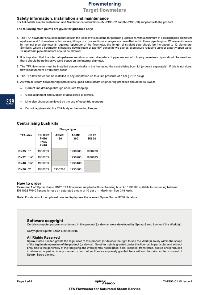
TFA size
Flange type
EN 1092
ASME
ASME
JIS 20
PN16
150
300
KS 20
PN25
PN40
DN25 1"
1930283
1930283 1930283
DN32 11⁄4"
1930283
1930283 1930283
DN40 11⁄2" 1930283 1930483
DN50 2"
1930283
1930283
1930583
Software copyright
Certain computer programs contained in this product [or device] were developed by Spirax-Sarco Limited ('the Work(s)').
Copyright © Spirax-Sarco Limited 2016
All Rights Reserved
Spirax-Sarco Limited grants the legal user of this product (or device) the right to use the Work(s) solely within the scope
of the legitimate operation of the product (or device). No other right is granted under this licence. In particular and without
prejudice to the generality of the foregoing, the Work(s) may not be used, sold, licensed, transferred, copied or reproduced
in whole or in part or in any manner or form other than as expressly granted here without the prior written consent of
Spirax-Sarco Limited.
Safety information, installation and maintenance
For full details see the Installation and Maintenance Instructions (IM-P193-02 and IM-P193-03) supplied with the product.
The following main points are given for guidance only:
1. The TFA flowmeter should be mounted with the 'concave' side of the target facing upstream, with a minimum of 6 straight pipe diameters
upstream and 3 downstream. No valves, fittings or cross sectional changes are permitted within these pipe lengths. Where an increase
in nominal pipe diameter is required, upstream of the flowmeter, the length of straight pipe should be increased to 12 diameters.
Similarly, where a flowmeter is installed downstream of two 90° bends in two planes, a pressure reducing valveor a partly open valve,
12 upstream pipe diameters should be allowed.
2. It is important that the internal upstream and downstream diameters of pipe are smooth. Ideally seamless pipes should be used and
there should be no intrusive weld beads on the internal diameter.
3. The TFA flowmeter must be installed concentrically in the line using the centralising bush kit (ordered separately). If this is not done,
flow measurement errors may occur.
4. The TFA flowmeter can be installed in any orientation up to a line pressure of 7 bar g (102 psi g).
5. As with all steam flowmetering installations, good basic steam engineering practices should be followed:
-
Correct line drainage through adequate trapping.
-
Good alignment and support of associated pipework.
-
Line size changes achieved by the use of eccentric reducers.
-
Do not lag (insulate) the TFA body or the mating flanges.
Centralising bush kits
How to order
Example: 1 off Spirax Sarco DN25 TFA flowmeter supplied with centralising bush kit 1930283 suitable for mounting between
EN 1092 PN40 flanges for use on saturated steam at 10 bar g - Maximum flow 349 kg/h.
Note: For details of the optional remote display see the relevant Spirax Sarco M750 literature.
Page 4 of 4
TI-P193-01 MI Issue 4
TFA Flowmeter for Saturated Steam Service

