Dimensions/weights (approximate) in mm and kg
Size
DN50
DN80
DN100
A
35
45
60
Flowmeter
C
OD
103
322
138
334
162
344
D
125
115
155
E
65
65
65
F
G
X
250
160
300
270
160
300
280
160
300
Weight
TVA
Superheat
kit
2.67
0.3
4.38
0.3
7.28
0.3
'U' syphon
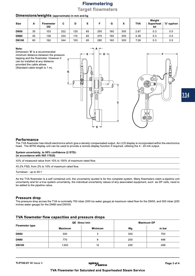
Note:
Dimension 'X' is a recommended
minimum distance between the pressure
tapping and the flowmeter. However it
can be installed at any distance
provided the cable allows
(Standard cable length is 1 m).
G
A
X
D
F
TVA flowmeter flow capacities and pressure drops
Flowmeter type
DN50
300
QE litres/min
MaximumDP
Wg
m bar
300
750
200
498
200
498
Maximum
DN80
770
Minimum
3
8
12
DN100
1 200
TI-P192-01 MI Issue 3
Page 3 of 4
Flowmetering
Target flowmeters
E
Performance
The TVA flowmeter has inbuilt electronics which give a density compensated output. An LCD display is incorporated within the electronics
head. The M750 display unit can be used to provide a remote display function if required, utilising the 4 - 20 mA output.
System uncertainty, to 95% confidence (2 STD):
(in accordance with ISO 17025)
±2% of measured value from 10% to 100% of maximum rated flow.
±0.2% FSD, from 2% to 10% of maximum rated flow.
Turndown : up to 50:1
As the TVA flowmeter is a self contained unit, the uncertainty quoted is for the complete system. Many flowmeters claim a pipeline unit
uncertainty and for a true system uncertainty, the individual uncertainty values of any associated equipment, such as DP cells, need to
be added to the pipeline value.
Pressure drop
The pressure drop across the TVA is nominally 750 mbar (300 ins water gauge) at maximum rated
flow for the DN50, and 500 mbar (200
inches water gauge) for the DN80 and DN100.
TVA Flowmeter for Saturated and Superheated Steam Service
C
0.5
0.5
0.5
3.3.4

