Flowmetering
Gilflo and ILVA flowmeters
Local regulations may restrict the use of this product to below the conditions quoted.
In the interests of development and improvement of the product, we reserve the right to change the specification without notice.
© Copyright 2014
TI-S41-10
MI Issue 10
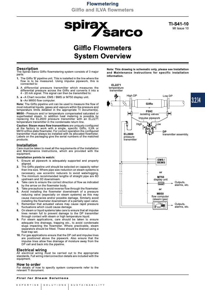
The Spirax Sarco Gilflo flowmetering system consists of 3 major
parts:
1. TheGilflo'B'pipelineunit.Thisisinstalledinthelinewherethe
flow is to be measured. Using impulse pipework, this is
connected to:
2. A differential pressure transmitter which measures the
differential pressure across the Gilflo and converts it into a
4 - 20 mA signal. This signal can then be transmitted to:
3. a - A Chart recorder, EMS / BMS or M750 display unit.
b - An M850 flow computer.
Note: The Gilflo pipeline unit can be used to measure the flow of
most industrial liquids, gases and vapours within the pressure and
temperature limits detailed in the appropriate TI document(s).
M850 - Pressure and / or temperature compensated saturated or
superheated steam. In addition heat metering is possible by
replacing the EL2600 pressure transmitter with an EL2271
temperature transmitter in the condensate return line.
Caution: Steam mass flow transmitters are uniquely configured
at the factory to work with a single, specific Gilflo, ILVA or
M410 orifice plate flowmeter. For correct operation the configured
transmitter must always be installed with its allocated flowmeter.
Labels on the packaging give the serial numbers of the matched
products.
Care must be taken to meet all the requirements of the Installation
and Maintenance Instructions, which are provided with the
equipment.
Installation points to watch:
1. Ensure all pipework is adequately supported and properly
aligned.
2. The Gilflo pipeline unit should be selected on capacity rather
than line size. Where pipe size reduction on steam systems is
necessary, use eccentric reducers to avoid waterlogging.
3. The minimum recommended lengths of straight pipe are 6D
upstream and 3D downstream.
4. Take care to ensure the correct direction of flow as indicated
by the arrow on the flowmeter body.
5. Take precautions to avoid reverse flow through the flowmeter.
6. Avoid installing the flowmeter downstream of a pressure
reducing valve (especially on steam systems) as this may
cause inaccuracies and/or possible damage. Similarly avoid
installing the flowmeter downstream of a partially open valve.
7. Remember that actuated valves may cause rapid pressure
fluctuations which could cause damage.
8. On steam or liquid systems take care to ensure that all impulse
lines remain full to prevent damage to the DP transmitter
through contact with steam or high temperature liquid.
9. For steam applications, care should be taken to ensure
adequate line drainage, trapping etc., to avoid condensate
slugs impacting the flowmeter. Where practicable, steam
separators should be fitted. These should be drained using a
float trap set.
10. For gas applications ensure that the DP cell and impulse lines
are positioned above the pipework. Also ensure that the
impulse lines allow free drainage of moisture away from the
DP cell and back into the pipeline.
All electrical wiring must be carried out to the appropriate
standards. Full wiring interconnection details are included with the
equipment.
For details of how to specify system components refer to the
relevant TI document.
EL2271
Gilflo Flowmeters
System Overview
Description
Note: This drawing is schematic only, please see Installation
and Maintenance Instructions for specific installation
information.
Low DP
transmitter assembly.
temperature
transmitter
High DP
Gilflo
F50C
isolating valves
Impulse pipework
High
Low
EMS /
BEMS
Installation
EL2600
DP
pressure
transmitter
or
M750
display unit
Outputs,
alarms, etc.
Outputs,
alarms, etc.
or
flow computer
(steam / gas)
M850
Electrical wiring
How to order
3.2.14

