Flowmetering
Gilflo and ILVA flowmeters
Mass flow units
Q
E
=
q
m
SG
Q=q
1000
E
M
D
F
Q
E
= Q
S
D
S
x
P
F
x
P
F
1000 P
S
T
S
3.2.11
Q
E
7750
78
10 975
110
15985
160
22637
226
22185
222
31 417
314
26915
269
38115
381
30 899
309
43758
438
36 043
433
51042
510
39 099
391
55 369
554
43 292
433
61307
613
49541
495
70157
702
55155
552
78 107
781
60 325
603
85428
854
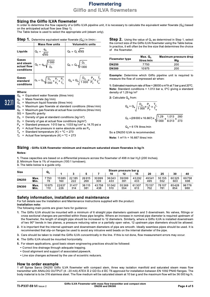
Sizing the Gilflo ILVA flowmeter
In order to determine the flow capacity of a Gilflo ILVA pipeline unit, it is necessary to calculate the equivalent water flowrate (Q
E
) based
on the anticipated actual flow (see Step 1).
The Table below is used to select the appropriate unit (steam only).
Step 1.
Determine equivalent water flowrate (Q
E
) in l/min:-
Volumetric units
Step 2.
Using the value of Q
E
as determined in Step 1, select
the correct size of the Gilflo ILVA flowmeter using the Table below.
In practice, it will often be the line size that determines the choice
of the flowmeter.
Liquids
Gases
and steam
actual flow
conditions
Gases
standard
conditions
Where:
Q
E
= Q
L
SG
D
E
Flowmeter type
DN250
DN300
Max. Q
E
litres /min
7 750
10 975
Maximum pressure drop
Wg
200
200
1000
F
Q
E
= Q
F
Q=
Q
S
x
S
x
F
Q
E
=
q
m
=
Q
L
=
Equivalent water flowrate (litres / min)
Mass flowrate (kg / min)
Maximum liquid flowrate (litres / min)
2: Calculate Q
E
from:
Q =Q
x
x D
P
P
D
P
S
1000 P T
Example: Determine which Gilflo pipeline unit is required to
measure the flow of compressed air when:
1: Estimated maximum rate of flow = 28000 s m3/h at 7 bar g and 20°C.
Note: Standard conditions = 1.013 bar a, 0°C giving a standard
density of 1.29 kg / m3
Ö
F
S
T
Q
Q
SG =
D
S
=
D
F
=
P
S
=
P
F
=
T
S
=
T
F
=
D
P
T
F
1000 P
S
T
S
= Maximum gas flowrate at standard conditions (litres / min)
S
S
F
S
E
S
1Q00
E
0=QP
S
T
S
x
F
x
F
= Maximum gas flowrate at actual flow conditions (litres / min)
Specific gravity
Density of gas at standard conditions (kg / m3)
Density of gas at actual flow conditions (kg/m3)
Standard pressure: 1
.
013 bar a, 1
.
033 kg / cm
2
a, 14.70 psi a
Actual flow pressure in same absolute units as P
S
Standard temperature (K) = °C + 273
Actual flow temperature (K) = °C + 273
Ö
Q
E
=(28000 x 16.667) x
Q
E
= 6 174 litres /min
So a DN250 ILVA is recommended.
Note: 1 m3/h = 16.667 litres/min
F
S
Sizing - Gilflo ILVA flowmeter minimum and maximum saturated steam flowrates in kg/h
Notes:
1. These capacities are based on a differential pressure across the flowmeter of 498 m bar H
2
0 (200 Inches).
2. Minimum flow is 1% of maximum (100:1 turndown).
3. The table below is a guide only.
1.29
x
1.013
x
293
1 000
8.013 273
Size
DN250
DN300
Steam pressure bar g
1
3
5
7
10
12
15
20
25
30
40
Max.
Min.
Max.
Min.
Safety information, installation and maintenance
For full details see the Installation and Maintenance Instructions supplied with the product.
Installation note:
The following main points are given here for guidance:
69 758
698
98 778
988
1. The Gilflo ILVA should be mounted with a minimum of 6 straight pipe diameters upstream and 3 downstream. No valves, fittings or
cross sectional changes are permitted within these pipe lengths. Where an increase in nominal pipe diameter is required upstream of
the flowmeter, the length of straight pipe should be increased to 12 diameters. Similarly, where a Gilflo ILVA is installed downstream
of two 90° bends in two planes, a pressure reducing valve or a partially open valve, 12 upstream pipe diameters should be allowed.
2. It is important that the internal upstream and downstream diameters of pipe are smooth. Ideally seamless pipes should be used. It is
recommended that slip-on flanges be used to avoid any intrusive weld beads on the internal diameter of the pipe.
3. Care should be taken to install the Gilflo ILVA concentrically in the line. If this is not done, flow measurement errors may occur.
4. The Gilflo ILVA should be mounted horizontally.
5. For steam applications, good basic steam engineering practices should be followed:
-
Correct line drainage through adequate trapping.
-
Good alignment and support of associated pipework.
-
Line size changes achieved by the use of eccentric reducers.
How to order example
1 off Spirax Sarco DN250 Gilflo ILVA flowmeter with compact stem, three way isolation manifold and saturated steam mass flow
transmitter with ANALOG OUTPUT (4 - 20 mA) ATEX II 2 GD Ex d IIC T6 approved for installation between EN 1092 PN40 flanges. The
body material is to be 316 stainless steel. The flow medium will be saturated steam at 10 bar g and the maximum flow will be 36 000 kg / h.
Gilflo ILVA Flowmeter with mass flow transmitter and compact stem
TI-P337-59 MI Issue 2
DN250 and DN300
Page 4 of 5

