Boiler house
Blowdown vessels
Table 1 Equivalent straight lengths
Table 3 Vent head selection
Note: The vent head required depends on the vessel selected
For a BDV60/3 select a VH4 vent head
For a BDV60/4 select a VH4 vent head
For a BDV60/5 select a VH6 vent head
For a BDV60/6 select a VH6 vent head
For a BDV60/8 select a VH8 vent head
For a BDV60/10 select a VH8 vent head
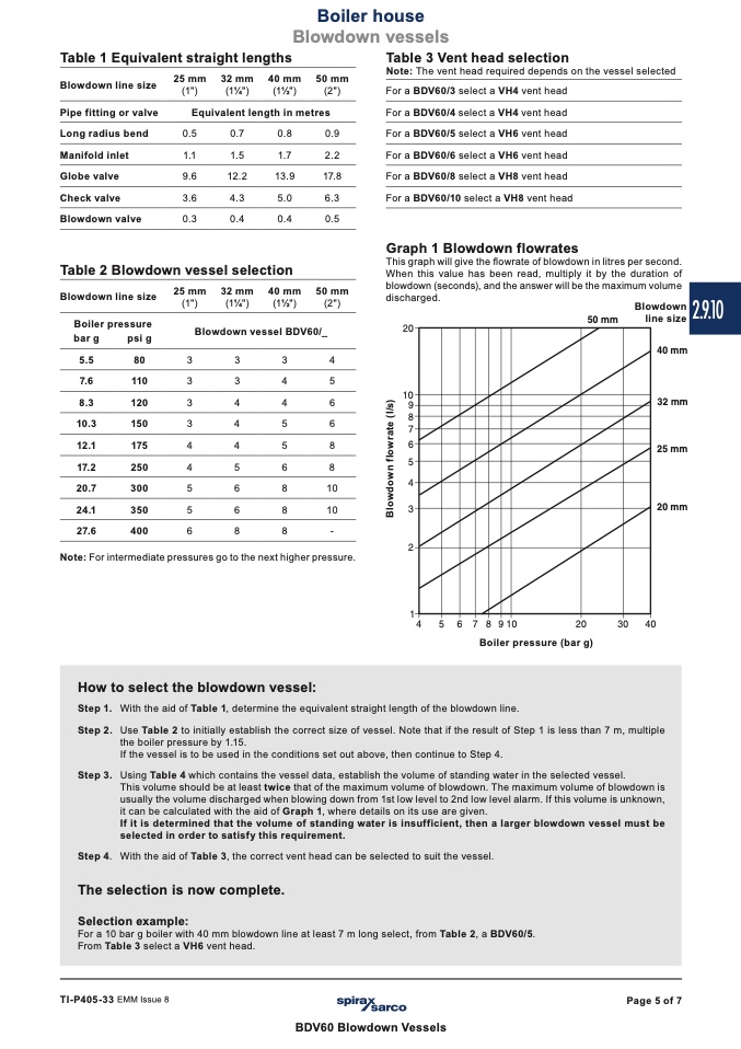
Graph 1 Blowdown flowrates
This graph will give the flowrate of blowdown in litres per second.
When this value has been read, multiply it by the duration of
blowdown (seconds), and the answer will be the maximum volume
discharged.
Blowdown
Blowdown line size
Pipe fitting or valve
Long radius bend
Manifold inlet
Globe valve
Check valve
Blowdown valve
25 mm 32 mm 40 mm
(1")
(11⁄4")
(11⁄2")
50 mm
(2")
0.5
1.1
9.6
3.6
0.3
0.7
0.8
1.5
1.7
12.2
13.9
4.3
5.0
0.4
0.4
0.9
2.2
17.8
6.3
0.5
50 mm
(2")
Equivalent length in metres
Table 2 Blowdown vessel selection
Blowdown line size
Boiler pressure
bar g
psi g
25 mm
(1")
32 mm
(11⁄4")
40 mm
(11⁄2")
Blowdown vessel BDV60/_
����
����
��
��
��
��
��
��
��
��
��
����������
����������
����������
����������
����������
line size
5.5
80
3
3
3
4
7.6
110
3
3
4
5
8.
3
12
0
3
4
4
6
10.3
150
3
4
5
6
12.1
175
4
4
5
8
17.2
250
4
5
6
8
20.7
300
5
6
8
10
24.1
350
5
6
8
10
27.6
400
6
8
8
-
Note: For intermediate pressures go to the next higher pressure.
�
�
�
�
�
�
����������
����
���
�
����
Boiler pressure (bar g)
How to select the blowdown vessel:
Step 1.
Step 2.
Step 3.
With the aid of Table 1, determine the equivalent straight length of the blowdown line.
Use Table 2 to initially establish the correct size of vessel. Note that if the result of Step 1 is less than 7 m, multiple
the boiler pressure by 1.15.
If the vessel is to be used in the conditions set out above, then continue to Step 4.
Using Table 4 which contains the vessel data, establish the volume of standing water in the selected vessel.
This volume should be at least twice that of the maximum volume of blowdown. The maximum volume of blowdown is
usually the volume discharged when blowing down from 1st low level to 2nd low level alarm. If this volume is unknown,
it can be calculated with the aid of Graph 1, where details on its use are given.
If it is determined that the volume of standing water is insufficient, then a larger blowdown vessel must be
selected in order to satisfy this requirement.
Step 4.
The selection is now complete.
With the aid of Table 3, the correct vent head can be selected to suit the vessel.
Selection example:
For a 10 bar g boiler with 40 mm blowdown line at least 7 m long select, from Table 2, a BDV60/5.
From Table 3 select a VH6 vent head.
TI-P405-33 EMM Issue 8
Page 5 of 7
BDV60 Blowdown Vessels
2.9.10
B
l
o
w
d
o
w
n
f
l
o
w
r
a
t
e
(
I
/
s
)

