General information
Local regulations may restrict the use of this product to below the conditions quoted.
Product limitations
In the interests of development and improvement of the product, we reserve the right to change the specification without notice. © Copyright 2016
TI-GCM-02
CM Issue 7
Pressure / Temperature Limits
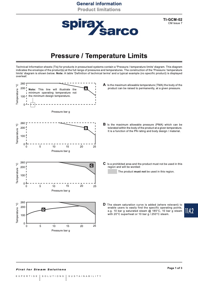
Technical Information sheets (TIs) for products in pressurised systems contain a 'Pressure / temperature limits' diagram. This diagram
indicates the envelope of the product(s) at the full range of pressures and temperatures. The construction of the 'Pressure / temperature
limits' diagram is shown below. Note: A table 'Definition of technical terms' and a typical example (no specific product) is displayed
overleaf.
������
������
������
��
������
������
Note: This line will illustrate the
minimum operating temperature not
the minimum design temperature.
Pressure bar g
A
B
A
Is the maximum allowable temperature (TMA) the body of the
product can be raised to permanently, at a given pressure.
B
Is the maximum allowable pressure (PMA) which can be
tolerated within the body of the product at a given temperature.
It is a function of the PN rating and body design / material.
C
Is a prohibited area and the product must not be used in this
region and will be worded:
The product must not be used in this region.
D
The steam saturation curve is added (where relevant) to
enable users to easily find the specific operating points,
e.g. 10 bar g saturated steam @ 185°C, 10 bar g steam
with 20°C superheat or 10 bar g / 250°C steam.
������
��
��
��
����
����
����
����
������
������
C
Pressure bar g
������
��
��
��
����
����
����
����
������
������
������
Pressure bar g
D
��
��
��
����
����
����
����
Pressure bar g
Page 1 of 3
11.4.2
T
e
m
p
e
r
a
t
u
r
e
°
C
T
e
m
p
e
r
a
t
u
r
e
°
C
T
e
m
p
e
r
a
t
u
r
e
°
C
T
e
m
p
e
r
a
t
u
r
e
°
C

