10.2.15
Shell length
(metres)
Shell
Ø
0.6, 1, 1.5 and 2 * 11⁄2", 2", 3" 4", 5", 6", 8" and 10"
1, 2 and 3 2", 3" 4", 5", 6", 8" and 10"
Heat transfer solutions
Heat exchangers
Local regulations may restrict the use of this product to below the conditions quoted.
In the interests of development and improvement of the product, we reserve the right to change the specification without notice.
© Copyright 2012
TI-P222-03
CH Issue 1
VEP and VES
Turflow Heat Exchangers
Description
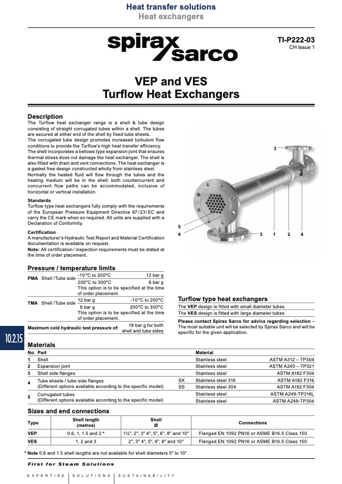
The Turflow heat exchanger range is a shell & tube design
consisting of straight corrugated tubes within a shell. The tubes
are secured at either end of the shell by fixed tube sheets.
The corrugated tube design promotes increased turbulent flow
conditions to provide the Turflow’s high heat transfer efficiency.
The shell incorporates a bellows type expansion joint that ensures
thermal stress does not damage the heat exchanger. The shell is
also fitted with drain and vent connections. The heat exchanger is
a gasket free design constructed wholly from stainless steel.
Normally the heated fluid will flow through the tubes and the
heating medium will be in the shell; both countercurrent and
concurrent flow paths can be accommodated, inclusive of
horizontal or vertical installation.
Standards
Turflow type heat exchangers fully comply with the requirements
of the European Pressure Equipment Directive 97/23/EC and
carry the CE mark when so required. All units are supplied with a
Declaration of Conformity.
Certification
A manufacturer’s Hydraulic Test Report and Material Certification
documentation is available on request.
Note: All certification/ inspection requirements must be stated at
the time of order placement.
12 bar g
6 bar g
specified at the time
-10°C to 200°C
200°C to 300°C
specified at the time
18 bar g for both
shell and tube sides
3
Pressure / temperature limits
PMA Shell /Tube side
-10°C to 200°C
5
4
3
1
2
4
Turflow type heat exchangers
The VEP design is fitted with small diameter tubes
The VES design is fitted with large diameter tubes
Please contact Spirax Sarco for advice regarding selection –
The most suitable unit will be selected by Spirax Sarco and will be
specific for the given application.
200°C to 300°C
This option is to be
of order placement.
TMA Shell /Tube side
12 bar g
6 bar g
This option is to be
of order placement.
Maximum cold hydraulic test pressure of:
Materials
No. Part
1 Shell
2 Expansion joint
3 Shell side flanges
Material
Stainless steel
Stainless steel
Stainless steel
Stainless steel 316
Stainless steel 304
Stainless steel
Stainless steel
Flanged EN 1092 PN16 or ASME B16.5 Class 150
Flanged EN 1092 PN16 or ASME B16.5 Class 150
Tube sheets / tube side flanges
(Different options available according to the specific model)
Corrugated tubes
(Different options available according to the specific model)
Sizes and end connections
Type
VEP
VES
SX
SS
ASTM A312 – TP304
ASTM A240 – TP321
ASTM A182 F304
ASTM A182 F316
ASTM A182 F304
ASTM A249-TP316L
ASTM A249-TP304
4
5
Connections
* Note 0.6 and 1.5 shell lengths are not available for shell diameters 5" to 10".

