Boiler house
Heat recovery systems
Local regulations may restrict the use of this product to below the conditions quoted.
In the interests of development and improvement of the product, we reserve the right to change the specification without notice. © Copyright 2014
2.8.15
Trap
pressure
bar g
0
0.5
1
1.5
Flash pressure bar g
2.5
3
4
5
6
7
8
9
10
% flash
2
25
24.5
22.6
21.2
20.0
18.9
18.0
17.2
15.7
14.4
13.3
12.2
11.3
10.4
9.5
24
24.1
22.2
20.7
19.5
18.5
17.6
16.7
15.3
14.0
12.8
11.8
10.8
9.9
9.0
23
23.6
21.7
20.3
19.1
18.0
17.1
16.3
14.8
13.5
12.3
11.3
10.3
9.4
8.5
22
23.2
21.3
19.8
18.6
17.6
16.6
15.8
14.3
13.0
11.8
10.8
9.8
8.9
8.0
21
22.7
20.8
19.3
18.1
17.1
16.1
15.3
13.8
12.5
11.3
10.3
9.3
8.4
7.5
20
22.2
20.3
18.8
17.6
16.6
15.6
14.8
13.3
12.0
10.8
9.7
8.7
7.8
6.9
19
21.7
19.8
18.3
17.1
16.0
15.1
14.2
12.7
11.4
10.2
9.2
8.2
7.2
6.4
18
21.2
19.3
17.8
16.6
15.5
14.5
13.7
12.2
10.8
9.7
8.6
7.6
6.7
5.8
17
20.6
18.7
17.2
16.0
14.9
14.0
13.1
11.6
10.3
9.1
8.0
7.0
6.1
5.2
16
20.1
18.2
16.7
15.4
14.3
13.4
12.5
11.0
9.7
8.5
7.4
6.4
5.4
4.5
15
19.5
17.6
16.1
14.8
13.7
12.8
11.9
10.4
9.0
7.8
6.7
5.7
4.8
3.9
14
18.9
16.9
15.4
14.2
13.1
12.1
11.2
9.7
8.4
7.1
6.0
5.0
4.1
3.2
13
18.2
16.3
14.8
13.5
12.4
11.4
10.6
9.0
7.6
6.4
5.3
4.3
3.3
2.4
12
17.5
15.6
14.1
12.8
11.7
10.7
9.8
8.3
6.9
5.7
4.6
3.5
2.6
1.7
11
16.8
14.8
13.3
12.0
10.9
10.0
9.1
7.5
6.1
4.9
3.8
2.7
1.8
0.9
10
16.1
14.1
12.5
11.3
10.1
9.2
8.3
6.7
5.3
4.1
2.9
1.9
0.9
-
9
15.2
13.2
11.7
10.4
9.3
8.3
7.4
5.8
4.4
3.2
2.0
1.0
-
-
8
14.4
12.3
10.8
9.5
8.4
7.4
6.5
4.9
3.5
2.2
1.1
-
-
-
7
13.4
11.4
9.8
8.5
7.4
6.4
5.4
3.8
2.4
1.2
-
-
-
-
6
12.3
10.3
8.7
7.4
6.3
5.2
4.3
2.7
1.3
-
-
-
-
-
5
11.2
9.1
7.5
6.2
5.0
4.0
3.1
1.4
-
-
-
-
-
-
4
9.8
7.7
6.1
4.8
3.6
2.6
1.7
-
-
-
-
-
-
-
3
8.3
6.2
4.5
3.2
2.0
0.9
-
-
-
-
-
-
-
-
2
6.3
4.2
2.6
1.2
-
-
-
-
-
-
-
-
-
-
1
3.8
1.7
-
-
-
-
-
-
-
-
-
-
-
-
LP Factor =
1.673 1.149 0.881 0.714
0.603
0.522 0.461 0.374 0.315 0.272
0.240
0.215
0.194
0.177
1000 kg/h
2000 kg/h
4000 kg/h
166 kg/h
202 kg/h
252 kg/h
2 bar g
16.6%
20 bar g
10 bar g
6 bar g
2 bar g
10.1%
2 bar g
6.3%
620 kg/h
67
138
243
385
560
5.6 m/s
2.7 m/s
1.6 m/s
1.0 m/s
0.7 m/s
FV6
FV8
3
FV12
FV15
FV18
620 kg/h
0.603
374 m
3
/h
AI-P404-12
AB Issue 3
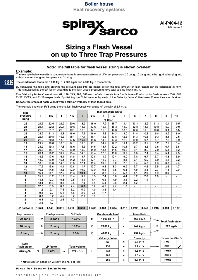
Example:
Sizing a Flash Vessel
on up to Three Trap Pressures
Note: The full table for flash vessel sizing is shown overleaf.
The example below considers condensate from three steam systems at different pressures, 20 bar g, 10 bar g and 6 bar g, discharging into
a flash vessel designed to operate at 2 bar g.
The condensate loads are 1 000 kg / h, 2 000 kg / h and 4 000 kg / h respectively.
By consulting the table and entering the relevant data into the boxes below, the total amount of flash steam can be calculated in kg/h.
This is multiplied by the 'LP factor' according to the flash vessel pressure to give total volume flow in m
3
/ h.
Five 'Velocity factors' are shown: 67, 138, 243, 385, 560 each of which relate to a 3 m / s take-off velocity for flash vessels FV6, FV8,
FV12, FV15, and FV18 respectively. By dividing the 'Total volume' by each of the 'Velocity factors', five take-off velocities are obtained.
Choose the smallest flash vessel with a take-off velocity of less than 3 m / s.
The example shows an FV8 being the smallest flash vessel with a take-off velocity of 2.7 m / s.
Trap pressure
Total
flash steam
Flash pressure
% Flash
Condensate load
Mass flash
* Velocity
X
=
Total flash steam
Choose on < 3 m / s
X
=
X
=
Velocity factor
=
X
=
÷
=
=
=
LP factor
Total volume
=
* Note: Size on a take-off velocity of 3 m / s or less.

