Boiler house
Heat recovery systems
M
2.8.13
B
L
M
J
L
K
B
J
G
K
L
B
J
K
E
G
E
G
M
E
D
C
D
C
D
C
H
H
H
A
A
A
F
F
F
FV6
FV8 and FV12
FV15 and FV18
Dimensions/weights (approximate) in ins, mm and kg
Installation
A
B
C
D
E
F
G
FV6
FV8
FV12
168
219
324
104
210
262
370
413
418
620
663
668
FV15
FV18
406
457
303
329
390
514
640
764
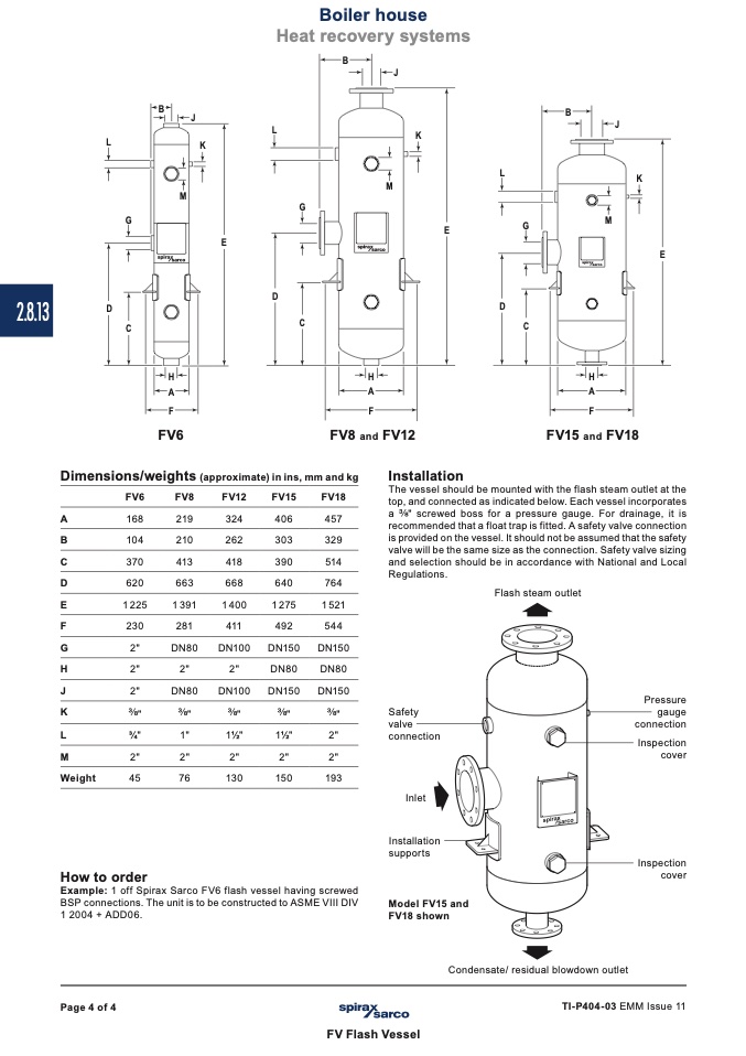
The vessel should be mounted with the flash steam outlet at the
top, and connected as indicated below. Each vessel incorporates
a " screwed boss for a pressure gauge. For drainage, it is
recommended that a float trap is fitted. A safety valve connection
is provided on the vessel. It should not be assumed that the safety
valve will be the same size as the connection. Safety valve sizing
and selection should be in accordance with National and Local
Regulations.
1225
1391
1400
1275
1521
230
281
411
492
544
2"
DN80
DN100
DN150
DN150
Flash steam outlet
H
2
"
2
"
2
"
DN8
0
DN80
J
2"
DN80
DN100
DN150
DN150
K
"
"
"
"
"
L
3⁄4"
1"
11⁄2"
11⁄2"
2"
M
2"
2"
2"
2"
2"
Safety
valve
connection
Inlet
Installation
supports
Model FV15 and
FV18 shown
Pressure
gauge
connection
Inspection
cover
Inspection
cover
Weight
45
76
130
150
193
How to order
Example: 1 off Spirax Sarco FV6 flash vessel having screwed
BSP connections. The unit is to be constructed to ASME VIII DIV
1 2004 + ADD06.
Condensate/ residual blowdown outlet
Page 4 of 4
TI-P404-03 EMM Issue 11
FV Flash Vessel

