Compressed air products
Isolation valves, drain traps and ancillaries
Dimensions / weights (approximate) in mm and kg
PN40
A
ASME 150
A
ASME 300
A
JIS/KS 20K
A
B
C
PN40
D
ASME 150/300
JIS/KS 20K
D
E
PN40
F
ASME 150/300
JIS/KS 20K
F
PN40
G
ASME 150/300
JIS/KS 20K
G
230
321
327
322
130
116
326
248
200
200
154
242
164
230
313
320
311
141
123
332
251
200
225
158
248
167
Size
DN40
DN50
Flange bolt hole tappings
Weight
33
43
G
Size
DN40
DN50
ASME 150
1⁄2" - 13 UNC - 2B
" - 11 UNC - 2B
ASME 300
3⁄4" - 10 UNC - 2B
" - 11 UNC - 2B
JIS/KS 20K
M16 x 2 - 6H
M16 x 2 - 6H
B
Safety information, installation and maintenance
For full details, see the Installation and Maintenance Instructions
(IM-P148-37) supplied with the product.
Installation note:
The trap must be fitted in the horizontal plane below what it is draining
with the direction of flow as indicated on the body so that the float
mechanism is free to rise and fall in a vertical plane.
One of the advantages of the float trap for draining air and gas
systems is that no bleed is required for satisfactory operation.
However, because the trap has no bleed a seperate balance line is
needed to prevent it becoming air or gas locked.
It should be noted that the balance line is piped back to the
upstream side.
A balance line is essential for the correct operation of this
product.
It is recommended that a non-return valve is fitted when discharging
condensate into return lines where backpressure is experienced. It
is also recommended that a diffuser is fitted when discharging to
atmosphere.
For convenience of maintenance it is recommended that a union is
fitted in the balance line near to the trap cover and consideration
should be given to fitting isolation valves upstream and downstream
of the trap.
The CA44S must not be insulated.
Disposal
The product is recyclable. No ecological hazard is anticipated with
the disposal of this product providing due care is taken.
How to order
Example: 1 off Spirax Sarco DN50 CA44S-32 air and gas trap flanged
to EN 1092-1 PN40 having a carbon steel body and cover.
Spare parts
C
F
E
A
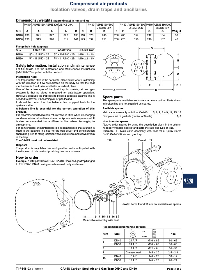
The spare parts available are shown in heavy outline. Parts drawn
in broken line are not supplied as spares.
Available spares
Main valve assembly with float CA44S
Complete set of gaskets (packet of 3 sets)
How to order spares
5, 6, 7, 8 + 9, 14, 15, 16
3, 6
D
Always order spares by using the description given in the column
headed 'Available spares' and state the size and type of trap.
Example: 1 - Main valve assembly with float for a Spirax Sarco
DN50 CA44S-32 air and gas trap.
*19
3
Dowel *2
*2
* Note: Items 2 and 19 are not available as spares.
8
9 715145166
Main valve assembly with float
Recommended tightening torques
Item
2
5
7
19
Size
DN40
DN50
DN40
DN50
or
mm
N m
60 - 66
80 - 88
50 - 55
2.5 - 2.8
10 - 12
20 - 24
24 A/F
M16
x 85
24 A/F
M16 x 85
17 A/F
M12 x 8
Cheesehead
M5 x 20
10 A/F
M6 x 20
13 A/F
M8 x 20
TI-P148-03 ST Issue 8
CA44S Carbon Steel Air and Gas Trap DN40 and DN50
Page 3 of 3
9.5.28

