A,D
Compressed air products
Isolation valves, drain traps and ancillaries
Local regulations may restrict the use of this product to below the conditions quoted.
In the interests of development and improvement of the product, we reserve the right to change the specification without notice.
© Copyright 2014
D
C
B
TI-P148-03
ST Issue 8
Description
CA44S
Carbon Steel
Air and Gas Trap DN40 and DN50
The CA44S is an carbon steel ball float air and gas trap. It has a metal valve cone and is available with horizontal flanged connections.
The cover will be drilled and tapped 3⁄4" BSP or NPT for the purpose of fitting a balance line. Body and cover castings are produced by a TÜV
approved supplier in accordance with AD-Merkblatt WO / TRD100.
Standards
This product fully complies with the requirements of the European Pressure Equipment Directive 97/23/EC and carries the mark when so
required.
Certification
The product is available with material certification to EN 10204 3.1. Note: All certification/inspection requirements must be stated at the time
of order placement.
Sizes and pipe connections
DN40 and DN50
Standard flanges are:
EN 1092-1 PN40 with DIN face-to-face dimensions and
ASME 150, ASME 300 and JIS/KS 20K flanges with drilled and
tapped bolt holes with DIN face-to-face dimensions.
PN and JIS/KS flanges will be provided with BSP balance line and
ASME flanges with NPT balance line.
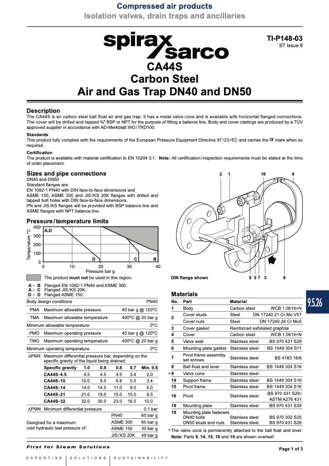
Pressure/temperature limits
������
������
������
������
��
A-B
A - C
D-D
2
1
16
4
��
����
����
����
����
Pressure bar g
The product must not be used in this region.
Flanged EN 1092-1 PN40 and ASME 300.
Flanged JIS/KS 20K.
Flanged ASME 150.
6 5 7 3
Body design conditions
PMA Maximum allowable pressure
TMA Maximum allowable temperature
Minimum allowable temperature
PMO Maximum operating pressure
TMO Maximum operating temperature
Minimum operating temperature
PN40
40 bar g @ 120°C
400°C @ 20 bar g
0°C
40 bar g @ 120°C
400°C @ 20 bar g
0°C
Material
DIN flange shown
Materials
No. Part
1
Body
2
Cover studs
Cover nuts
3
Cover gasket
4
Cover
5
Valve seat
8
Carbon steel
Steel
DN 17240 21 Cr Mo V57
Steel
DN 17240 24 Cr Mo5
Reinforced exfoliated graphite
WCB 1.0619+N
Carbon steel
Stainless steel
Stainless steel
Stainless steel
Stainless steel
Stainless steel
Stainless steel
Stainless steel
Stainless steel
Stainless steel
Note: Parts 9, 14, 15, 18 and 19 are shown overleaf.
Page 1 of 3
WCB 1.0619+N
BS 970 431 S29
BS 1449 304 S11
BS 4183 18/8
BS 1449 304 S16
BS 1449 304 S16
BS 1449 304 S16
BS 970 431 S29/
ASTM A276 431
BS 970 431 S29
DPMX Maximum differential pressure bar, depending on the
specific gravity of the liquid being drained:
6
Mounting plate gasket
7
Pivot frame assembly
set screws
8
Ball float and lever
* 9
Valve cone
14 Support frame
15 Pivot frame
16 Pivot
18 Mounting plate
19 Mounting plate fasteners
DN40 bolts
DN50 studs and nuts
* The valve cone is permanently attached to the ball float and lever.
Specific gravity 1.0
CA44S - 4.5
4.5
CA44S - 10
10.0
CA44S - 14
14.0
CA44S - 21
21.0
CA44S - 32
32.0
0.9
0.8 0.7
4.5
4.5
3.4
9.5
6.8
5.5
14.0 11.0
8.0
19.0 15.0 10.0
30.0 23.0 16.5
Min. 0.6
2.0
3.4
5.0
6.5
10.0
0.1 bar
60 bar g
60 bar g
30 bar g
49 bar g
DPMN Minimum differential pressure
PN40
Stainless steel
Stainless steel
BS 970 302 S25
BS 970 431 S29
Designed for a maximum
cold hydraulic test pressure of:
ASME 300
ASME 150
JIS/KS 20K
9.5.26
T
e
m
p
e
r
a
t
u
r
e
°
C

