Compressed air products
Isolation valves, drain traps and ancillaries
Dimensions / weight (approximate) in mm and kg
A
B
C
D
E
F
Weight
Spare parts
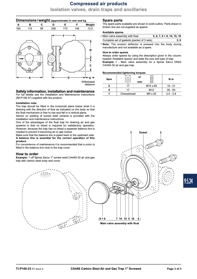
The spare parts available are shown in solid outline. Parts drawn in
broken line are not supplied as spares.
165
115
85
208
170
146
12.5
F
Available spares
* Main valve assembly with float
Complete set of gaskets (packet of 3 sets)
5, 6, 7, 8 + 9, 14, 15, 16
3, 6
B
* Note: The erosion deflector is pressed into the body during
manufacture and not available as a spare.
A
D
E
Item
or
N m
How to order spares
Always order spares by using the description given in the column
headed 'Available spares' and state the size and type of trap.
Example: 1 - Main valve assembly for a Spirax Sarco DN25
C
CA44S-32 air and gas trap.
Recommended tightening torques
Withdrawal
distance
Safety information, installation and maintenance
For full details see the Installation and Maintenance Instructions
(IM-P148-37) supplied with the product.
Installation note:
The trap should be fitted in the horizontal plane below what it is
draining with the direction of flow as indicated on the body so that
the float mechanism is free to rise and fall in a vertical plane.
Advice on welding of socket weld variants is provided with the
installation and maintenance instructions.
One of the advantages of the float trap for draining air and gas
systems is that no bleed is required for satisfactory operation.
However, because the trap has no bleed a separate balance line is
needed to prevent it becoming air or gas locked.
Make sure that the balance line is piped back to the upstream side.
A balance line is essential for the correct operation of this
product.
For convenience of maintenance it is recommended that a union is
fitted in the balance line near to the trap cover.
How to order
Example: 1 off Spirax Sarco 1" socket weld CA44S-32 air and gas
trap with carbon steel body and cover.
mm
2
5
7
17
M10 x 60
19 - 21
50 - 55
2.5 - 2.8
17
M12
Cheesehead
M5 x 20
3
Dowel
2
7 14 15 5 16 6
Main valve assembly with float
8 + 9
TI-P148-23 ST Issue 4
CA44S Carbon Steel Air and Gas Trap 1" Screwed
Page 3 of 3
9.5.24

