Compressed air products
Regulators
53
9.2.7
54
A
B
B
A
Optional extras
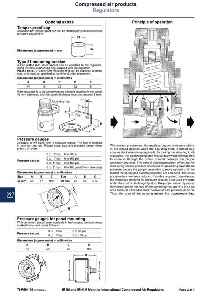
Principle of operation
Tamper-proof cap
An aluminium tamper-proof cap can be fitted to prevent unauthorised
pressure adjustment
Dimensions (approximate) in mm
Type 21 mounting bracket
A zinc plated mild steel bracket can be attached to the regulator,
using the plastic mounting ring supplied with the regulator.
Please note: An aluminium mounting ring can be supplied, at extra
cost, and must be specified at the time of order placement.
Dimensions (approximate) in millimetres
A
B
C
D
E
44
19
32
12
6
If the regulator is to be panel mounted a hole is required in the panel
48 mm diameter, and the panel thickness must not exceed 8 mm.
Mounting ring
E
D
C
B
A
Pressure gauges
Available in two sizes, with 4 pressure ranges. The face is marked
in both bar and psi. Please state, size and pressure range when
placing an order.
With system pressure on, the regulator poppet valve assembly is
in the closed position when the adjusting knob is turned fully
counter clockwise (no spring load). By turning the adjusting knob
clockwise, the diaphragm / piston moves downward allowing flow
to come in through the orifice created between the poppet
assembly and seat. The control diaphragm / piston offsetting the
load spring senses pressure downstream. Increasing downstream
pressure causes the poppet assembly to move upward until the
load of the spring and diaphragm / piston are balanced. The outlet
pressure has now been reduced. If a valve is opened downstream,
the increased demand for pressure creates a reduced pressure
under the control diaphragm / piston. The poppet assembly moves
downward due to the load of the control spring opening the seat
area and air is allowed to meet the downstream pressure demand.
Thus, the area of the opening meters the downstream flow.
Pressure ranges
0 to
0 to
0 to
0 to
2 bar
7 bar
11 bar
21 bar
0 to 30 psi
0 to 100 psi
0 to 160 psi
0 to 300 psi (50 mm size only)
Dimensions (approximate) in millimetres
Size
A
B
C
Size
A
B
C
40 mm 40
47
R "
50 mm 49
45
R "
C
Pressure gauges for panel mounting
With chromium plated bezel available in two ranges, the face being
marked in bar and psi as follows:-
Pressure ranges
0 to 2 bar
0 to 30 psi
0 to 7 bar
0 to 100 psi
Dimensions (approximate) in millimetres
A
B
C
D
53
56
48
R
D
C
TI-P504-19 CH Issue 2
IR1M and IRN1M Monnier International Compressed Air Regulators
Page 2 of 4

