Steam consumption
Pipeline ancillaries
Hosedown stations
Litres / minute
������
1⁄2"
Maximum ����
flow of
heated water
����
Example:
����
Maximum
flow of
cold water
Capacities
Steam usage is shown in kg/h with the maximum water flow. If the water flow
reduces then the steam usage will also decrease.
��������
��������
��������
��������
��������
��������
Steam flow kg/h (with maximum water flow)
Example:
Pressure bar
0.5
1
2
3
4
5
6
7
8
9
10
1⁄2"
3⁄4"
Valve type
1"
11⁄2"
45
100
180
185
60
125
300
245
90
175
380
440
135
270
450
565
160
310
520
715
175
335
580
820
Sizes and capacities
������
������
������
����
��
������
������
������
������
��
������
������
������
������
������
��
3⁄4"
180
380
600
210
445
665
225
515
735
245
550
830
260
570
905
950
1 070
1 165
1 240
1 290
��
�� �� �� �� �� �� �� �� �� �� ����
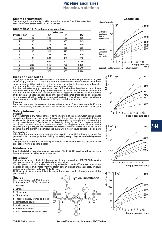
The graphs indicate the maximum flow of hot water at various temperatures for a given
steam supply pressure. The bold lines show the maximum cold water flow for a given water
supply pressure. When sizing the valve, ascertain the hot water temperature and quantity
required, and the cold water and steam pressures available.
Plot the cold water supply pressure and read off from the bold line the maximum flow of
cold water. Plot the steam supply pressure against the hot water temperature required and
read off the maximum flow of heated water. For sizing purposes always select the lowest
of the two values because depending on the supply pressures, there can be an imbalance
in the amount of either water or steam heat available. The effect of selecting different
supply pressures or different sizes of valve can easily be compared.
Example
For a cold water supply pressure of 3 bar g the maximum flow of cold water is 40 l/min.
For a steam supply pressure of 6 bar g the maximum flow of hot water at 50°C is 46 l/min.
Safety information
Pressure
Before attempting any maintenance of any component of the steam/water mixing station
consider what is or may have been in the pipeline. Ensure that any pressure is isolated and
safely vented to atmospheric pressure before attempting to maintain any component e.g.
mixing valve, hose etc. This is easily achieved by fitting Spirax Sarco depressurisation
valves type DV (see separate literature for details). Discharge content of hose and station
by pulling the gun trigger and eliminate the pressure until the water flow stops. Do not
assume that the system is depressurised even when the pressure gauges indicate zero.
Allow time for temperature to normalise after isolation to avoid the danger of burns. For
personal protection wear protective clothing, especially heavy duty gloves and safety glasses.
Disposal
This product is recyclable. No ecological hazard is anticipated with the disposal of this
product providing due care is taken.
See the Installation and Maintenance Instructions (IM-P157-03) supplied with each system
before commencing with any maintenance.
Installation
Full details are given in the Installation and Maintenance Instructions (IM-P157-03) supplied
with each system. A typical installation is shown below.
Supply pipework should be sized according to standard practice.The steam inlet should
be sized on the steam flowrate (from the steam consumption chart) at the supply pressure
and a steam velocity of between 15 to 25 m/s.
�� �� �� �� �� �� �� �� �� �� ����
Supply pressure bar g
1"
��������
��������
��������
��������
��������
��������
�� �� �� �� �� �� �� �� �� �� ����
Supply pressure bar g
11⁄2"
��������
��������
��������
��������
��������
��������
7.14.4
Temperature
Maintenance
Cold water pipework should take into account pressure, length of pipe and acceptable
pressure drop.
Spares
5
See Installation and Maintenance
Instructions IM-P157-03 for details.
Typical installation
5
1 Ball valve
2 Strainer
1
1
3 Steam trap
4 Check valve
5 Pressure gauge, syphon and cock
6 Temperature gauge
7 Mixingvalve
8 Mixed water outlet
9 TCO1 temperature cut-out valve
2
4
7
8
4
9
2
TI-P157-06 ST Issue 9
Steam / Water Mixing Stations - MkII Valve
3
6
�� �� �� �� �� �� �� �� �� �� ����
Supply pressure bar g
Example: Cold water supply
Steam supply
bar g
��������
��������
��������
��������
��������
��������
Supply pressure
L
i
t
r
e
s
/
m
i
n
u
t
e
L
i
t
r
e
s
/
m
i
n
u
t
e
L
i
t
r
e
s
/
m
i
n
u
t
e

